Component Replacement
48
17730-241
AR2
™
40K • 46K
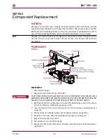
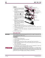
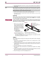
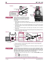
FIguRE 8‑15
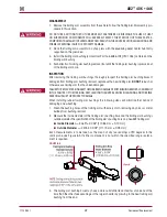
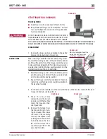
28 . Apply Loctite 262
ONLY
on the
upper half area of the saddle
cap stud that inserts into the trail-
ing arm .
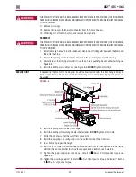
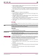
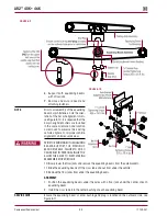
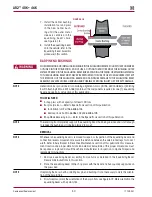
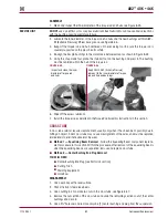
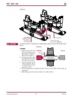
29 . Tighten the
saddle cap
fasteners
evenly in 50 foot pounds incre-
ments in the proper sequence for
uniform bolt tension as shown in
Figure 8-16 until the final torque
value of 250 ± 25 foot pounds
torque is achieved .
dO NOT
exceed specified torque on saddle
cap fasteners . Maintain an even
gap between the trailing arm assembly and saddle cap, see Figure 8-14 .
FIguRE 8‑16
NOTE
Tightening the saddle cap stud fasteners properly will help prevent wear
of mating components, beam center bushing, trailing arm assembly, and
saddle cap .
30 . Install the tires .
31 . Remove the supports from the drive axles and lower the vehicle onto the
ground .
32 . Remove the wheel chocks .
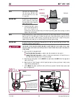
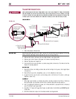
CENTER BuSHINg
YOu wILL NEEd
■
A shop press with a capacity of at least 100 tons
■
Center bushing tool — (Hendrickson Part No . 66086-100) – Refer to Special Tools section of
this publication for the tools to remove and install the rubber center bushings
■
Receiving tool — The receiving tool is a shop made tool which completely supports the beam
hub being serviced and is tall enough to receive the bushing as it is being pressed in or out,
refer to the Special Tools section of this publication
DISCARD USED FASTENERS . ALWAYS USE NEW FASTENERS TO COMPLETE A REPAIR . FAILURE TO DO SO
COULD RESULT IN FAILURE OF THE PART OR MATING PARTS, ADVERSE VEHICLE HANDLING, PERSONAL
INjURY, OR PROPERTY DAMAGE .
dISASSEMBLY
NOTE
Whenever an equalizing beam is removed for repair, or inspection of the equalizing beam end
connection reveals movement, measure the distance between the axle bracket legs for correct
width . Refer to Axle Bracket in Preventive Maintenance section of this publication for measure-
ment location and proper dimensions . An axle bracket outside of the proper dimensions must
be repaired or replaced . Consult the vehicle manufacturer for inspection, component repair and
replacement instructions .
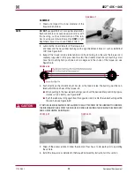
1 . Remove the equalizing beam assembly from the vehicle . Follow the equalizing beam disas-
sembly procedure in this section .
DO NOT USE A CUTTING TORCH TO REMOVE ANY FASTENERS OR BUSHINGS . THE USE OF HEAT
ON SUSPENSION COMPONENTS WILL ADVERSELY AFFECT THE STRENGTH OF THESE PARTS . A
COMPONENT DAMAGED IN THIS MANNER CAN RESULT IN THE ADVERSE VEHICLE HANDLING AND
POSSIBLE PERSONAL INjURY OR PROPERTY DAMAGE .


