Component Replacement
60
17730-241
AR2
™
40K • 46K
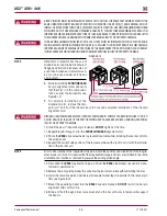
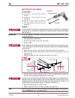
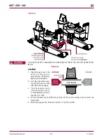
FIguRE 8‑41
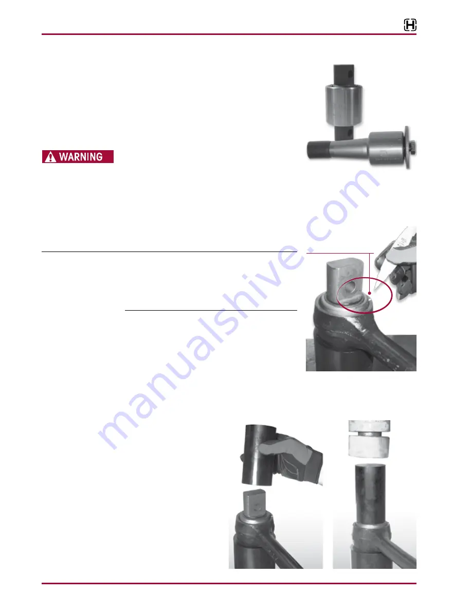
xTRB TORquE ROd BuSHINgS
YOu wILL NEEd
■
A vertical press with a capacity of at least 10 tons
■
Shop made receiving tool and installation / removal
tool, see the Special Tools section of this publication
for more information
DO NOT USE HEAT OR USE A CUTTING TORCH TO REMOVE
THE BUSHINGS FROM THE TORQUE ROD . THE USE OF HEAT
WILL ADVERSELY AFFECT THE STRENGTH OF THE TORQUE
ROD, HEAT CAN CHANGE THE MATERIAL PROPERTIES . A COMPONENT DAMAGED IN THIS MANNER CAN
RESULT IN ADVERSE VEHICLE HANDLING AND POSSIBLE PERSONAL INjURY OR PROPERTY DAMAGE .
dISASSEMBLY
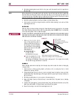
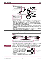
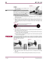
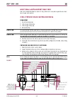
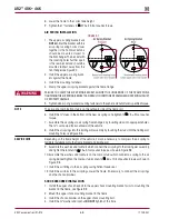
FIguRE 8‑42
1 . Remove the torque rod(s) as detailed in Torque Rod
Disassembly instructions in this section .
SERVICE HINT
When servicing a straddle mount bar pin bushing assem-
bly, mark the clocking position of the straddle mount bar
pin flats with a paint stick on the torque rod end hub prior
to disassembly, see Figure 8-42 . This marking will serve as
a guide when installing the new bushing assembly so the
original clocking position can be retained .
2 . Mark the clocking position of the straddle mount bar
pin flats with a paint stick on the torque rod end hub
prior to disassembly, see Figure 8-42 .
3 . Support the torque rod end hub centered on the receiv-
ing tool . Be sure the torque rod is squarely supported on
the press bed for safe ty .
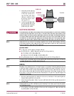
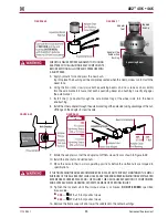
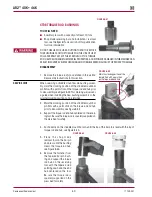
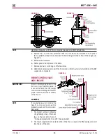
4 . Push directly on the straddle mount bar pin, until the top of the bar pin is level with the top of
torque rod end hub, see Figure 8-43 .
FIguRE 8‑43
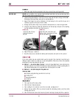
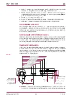
FIguRE 8‑44
5 . P l a c e t h e s h o p m a d e
removal tool on the bar pin
and press until the bushing
clears the torque rod hub,
see Figure 8-44 .
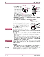
6 . Remove the fastener from
the tapered bar pin bush-
ing, and support the torque
rod hub on the receiving
tool with the tapered stud
pointing down and the end
hub centered on the tool .
Be sure the torque rod is
squarely supported on the
press bed for safety .
Mark the clocking position of the
bar pin flats with a paint stick
on the torque rod end hub

