17730-241
29
Alignment & Adjustments
AR2
™
40K • 46K
4 . When checking or adjusting ride height, verify and maintain the vehicle’s air system at full
operating pressure .
SERVICE HINT
It is important that the height control valves be cycled completely before and after any ride height
adjustments . The cycling of the height control valves will help to make the adjustment more accurate .
PRIOR TO AND DURING DEFLATION AND INFLATION OF THE AIR SUSPENSION SYSTEM, ENSURE THAT ALL
PERSONNEL AND EQUIPMENT ARE CLEAR FROM UNDER THE VEHICLE AND AROUND THE SERVICE AREA,
FAILURE TO DO SO CAN CAUSE SERIOUS PERSONAL INjURY, DEATH, OR PROPERTY DAMAGE .
SOME VEHICLE APPLICATIONS, SUCH AS VEHICLES EQUIPPED WITH OUTRIGGERS, RETAIN SOME AIR
PRESSURE IN THE AIR SPRINGS AT ALL TIMES . PRIOR TO PERFORMING ANY MAINTENANCE, SERVICE,
OR REPAIR OF THE SUSPENSION, VERIFY EACH AIR SPRING IS COMPLETELY DEFLATED . FAILURE TO DO
SO COULD RESULT SERIOUS PROPERTY DAMAGE AND / OR SEVERE PERSONAL INjURY .
5 . See additional Air Spring Cautions and Warnings in the Important Safety Notice section of this
publication prior to deflating or inflating the air system .
6 . Detach the upper rubber grommets of the height control valve linkages from the height control
valve arms and exhaust the suspension system air by lowering the height control valve arms .
7 . Refill the suspension by raising the height control valve arms by hand, so that the air springs
are above the proper ride height .
8 . Lower the height control valve arms to exhaust the suspension air system until the suspension
is at proper ride height .
NOTE
Adjustments to one (1) height control valve may affect ride height setting on the other height control
valve . Verify ride height is correct at both height control valves whenever an adjustment is made .
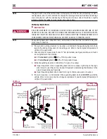
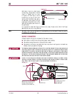
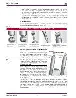
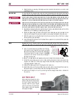
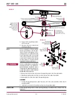
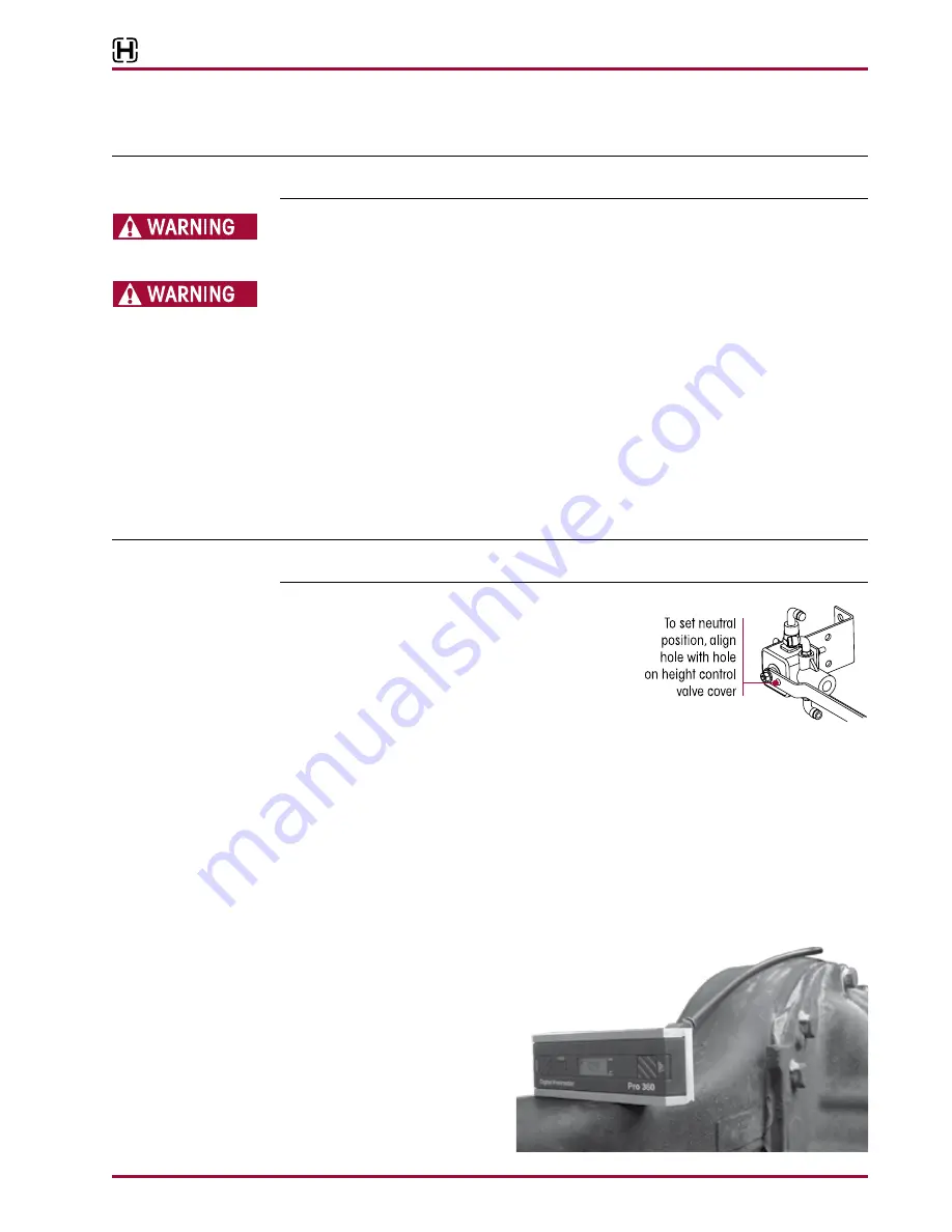
FIguRE 7‑3
9 . Use a
1
⁄
8
" wooden dowel rod (golf tee) to set the neu-
tral position for each height control valve by aligning
the hole in the leveling arm with the hole in the height
control valve cover, as shown in Figure 7-3 .
dO NOT
use a metal rod or nail as this may cause damage to
the height control valve .
10 . Steps 7 to 9 might need to be repeated using one (1) height control valve at a time .
11 . Correct the adjustable valve arm joints so the rubber grommets can be reconnected to the
height control valve arms at the proper height . Check the rubber components for any tearing
or damage, replace as necessary .
12 . Connect the rubber grommets to the height control valve arms .
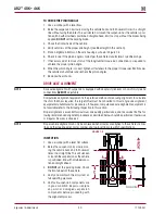
13 . Tighten the clamps on the adjustable valve arm joints with a screwdriver until securely fas-
tened, see Figure 7-1 . Remove the dowel from the height control valves .
14 . Verify the ride height is correct by performing the Ride Height Inspection as detailed in
this section .
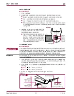
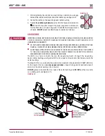
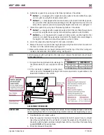
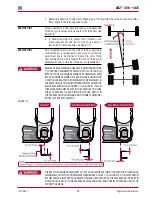
FIguRE 7‑4
AxLE pINION ANgLE
Drive axle pinion angles are estab-
lished by the vehicle manufacturer .
If pinion angle adjustment is
required, check for proper angles
with the vehicle manufacturer .
Pinion angle is set by the longitudi-
nal torque rod length .


