Preventive Maintenance
16
17730-299
ULTIMAAX
®
for Fire and Rescue Vehicles
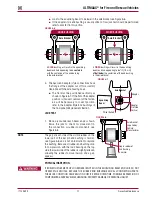
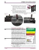
FIGURE 6-4
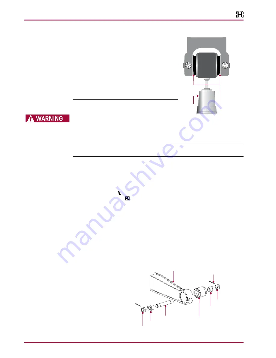
JACK TEST
1 . Place a jack under each beam end as shown . Raise the
jack to check for movement in the connection or rubber
components, see Figure 6-4 .
NOTE
The gap at each side of the visible rubber on the lower
part of the end bushing is normal, see Figure 6-4, and is
not an indication to replace the bushing . Because all rubber
end bushings are in compression, with the load bearing on
the top side, the lower side of the rubber is slightly relieved,
allowing the rubber to move inward, and a gap appears .
PHYSICAL INSPECTION
IF BAR PIN MOVEMENT OR LOOSENESS IS NOTED IN ANY OF
THE EQUALIZING BEAM END HUBS, DO NOT OPERATE THE VEHICLE . REPLACE THE RUBBER END
BUSHINGS AND ALL CONNECTING PARTS IF NECESSARY . THE ABOVE CONDITION CAN RESULT
IN COSTLY REPAIR, DOWNTIME, POSSIBLE SEPARATION OF COMPONENTS, ADVERSE VEHICLE
HANDLING, PROPERTY DAMAGE, OR PERSONAL INJURY .
SERVICE HINT
An equalizing beam end connection that is visibly cleaner than the other connections may indi-
cate a loose connection .
2 . If bar pin end bushing movement or looseness is detected in the equalizing beam end hub,
replace the end bushings and all connecting parts . Refer to the Component Replacement
Section of this publication .
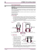
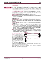
3 . Check and record torque values, as received, for each 1" bar pin fastener, see Figure 6-2 .
Ensure all fasteners are tightened to:
■
At the
locknut
to 525 ± 75 foot pounds torque, or
■
At the
bolt head
to 575 ± 75 foot pounds
4 . R e c h e c k e q u a l i z i n g beam end connections for signs of looseness .
■
Inspect alignment shims in equalizing beam end for looseness . Lightly tap on the align-
ment shims to see if they can be moved . If movement is detected, tighten fasteners to the
proper torque value, see Figure 6-2 .
■
Inspect equalizing beam end connection for signs of excessive wear or looseness .
5 . If bar pin looseness is still detected in any of the equalizing beam end hub,
DO NOT
operate
the vehicle . One or more components will require replacement, see Component Replacement
Section of this publication .
■
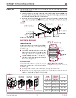
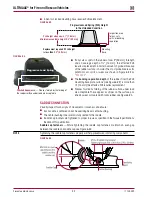
Adapter Style,
see Figure 6-5
FIGURE 6-5
VISUAL INSPECTION
1 . Chock the wheels .
2 . Visually inspect suspension
components for signs of
movement or excessive wear .
■
Inspect the equalizing
beam end connection
for signs of excessive
wear or looseness .
■
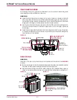
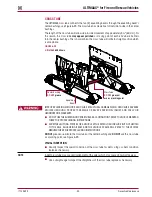
Look for worn, frayed or
distorted rubber in the beam, see Figure 6-6 .
Axle Bracket
Gap in rubber
of bar pin end
bushing is
normal
Floor
Jack
Equalizing
Beam
Adapter Style
End Bushing
Beam End Adapter
Beam End Shaft
1 / " Slotted Nut
7
8
Beam End Adapter
1 / " Slotted Nut
7
8
Cotter Pin
63K Shown
ULTIMAAX


