17730-299
29
Alignment & Adjustments
ULTIMAAX
®
for Fire and Rescue Vehicles
AXLE LATERAL ALIGNMENT
1 . Use a work bay with a level floor .
2 . Drive the vehicle slowly, straight ahead . Try to slacken or loosen the suspension as the vehicle
is positioned . End with all wheels positioned straight ahead . Try to roll to a stop without the
brakes being used .
DO NOT
set the parking brake .
3 . Chock the front wheels of the vehicle .
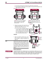
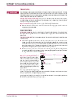
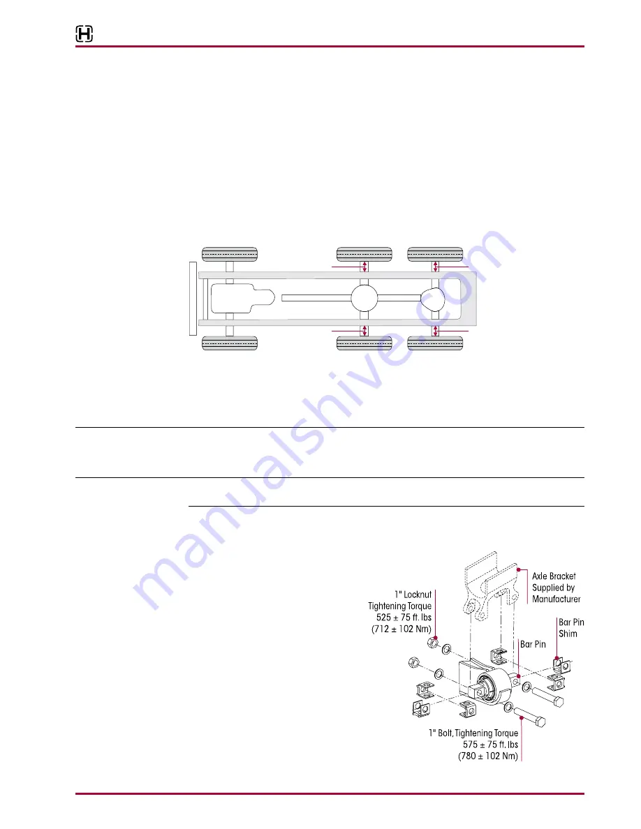
4 . Measure from the outside of the frame rail to the rim flange of the inner tire . Record the mea-
surement
A
and
B
, see Figure 7-3 .
5 . Measure the same distance on the opposite side of the same axle . Record the measurement
C
and
D
, see Figure 7-3 .
FIGURE 7-3
6 . Verify the axle lateral alignment is within the vehicle manufacturer’s specifications . Adding
or removing shims that are located between the transverse torque rod and the frame rail will
normally correct the axle lateral alignment .
■
A general rule of thumb is to use a torque rod shim with a thickness that is half of the dif-
ference between the two measurements .
EXAMPLE
If the axle lateral alignment is out of specification by ¼" (6 mm), remove or install a
1
⁄
8
" (3 mm)
torque rod shim between the transverse torque rod and frame rail as needed . Refer to Longitudinal
and Transverse Torque Rod Section in Preventive Maintenance Section of this publication .
NOTE
Hendrickson recommends the use of Grade 8 bolts and Grade C locknuts . Washers are not neces-
sary when flanged fasteners are used .
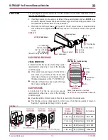
BAR PIN ALIGNMENT
FIGURE 7-4
The alignment feature consists of spe-
cially designed, tightly tolerance steel
shims which fill the
3
⁄
8
" (9 .5 mm) total
gap between the bushing’s bar pin and
the axle bracket legs . The gap must be
filled by placing the shims on the bushing
assembly in one of the positions shown
in Figure 7-4 . Hendrickson has three shim
designs options for alignment, part num-
ber 50130-000 (provided), 50131-000
and 57026-000, see Figure 7-7 .
FRONT
A
B
C
D
▲


