


Alignment & Adjustments
30
17730-299
ULTIMAAX
®
for Fire and Rescue Vehicles
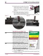
A BAR PIN SHIM MUST BE INSTALLED AT EACH BOLT LOCATION . THE SAME PART NUMBER SHIM IN THE
SAME ORIENTATION MUST BE USED AT BOTH BOLT LOCATIONS ON ANY ONE END BUSHING . DO NOT
INSTALL OR STACK MORE THAN ONE SHIM AT EACH BOLT LOCATION . USE GENUINE HENDRICKSON BAR
PIN SHIMS, DO NOT USE STANDARD WASHERS . FAILURE TO FOLLOW THESE WARNINGS MAY RESULT IN
IMPROPER VEHICLE ALIGNMENT, FRACTURE OF THE AXLE BRACKET OR BAR PIN WHICH COULD RESULT
IN THE ADVERSE VEHICLE HANDLING AND POSSIBLE PERSONAL INJURY OR PROPERTY DAMAGE .
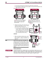
ALIGNMENT ADJUSTMENT
FIGURE 7-5
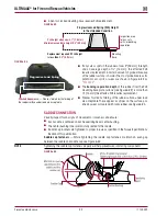
If alignment of the drive axles is required, as determined by an
alignment inspection procedure, the following steps will need
to be performed .
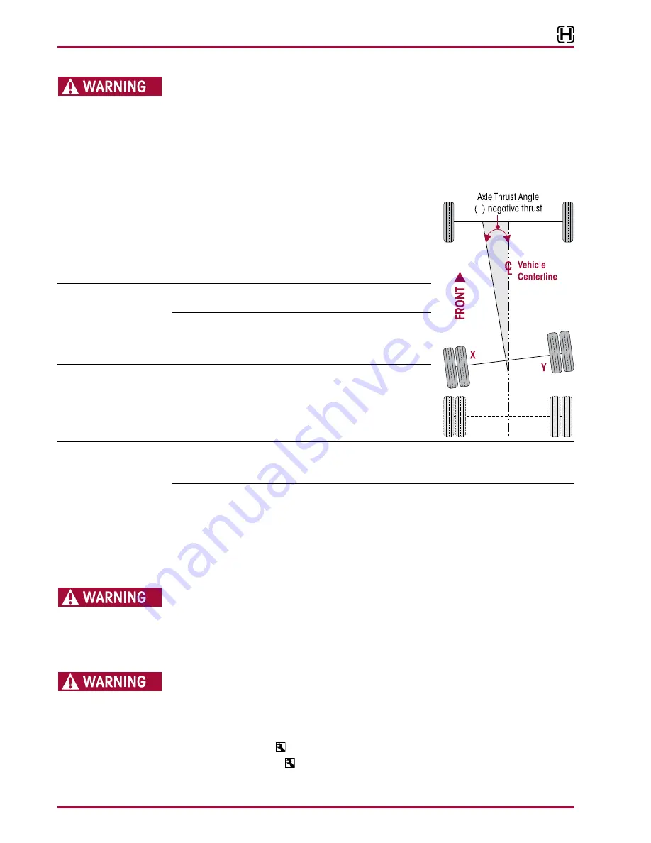
1 . Determine direction of axle thrust angle . Figure 7-5 illus-
trates the forward drive axle with a thrust angle to the left
(-negative thrust) .
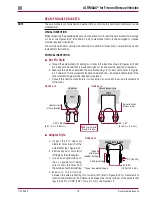
SERVICE HINT
Axle movement is in the same direction as the increased shim
thickness, see Figure 7-6 .
2 . To determine where to adjust shim thickness use measure-
ment
A
and
B
for front drive axle or
C
and
D
for rear drive
axle, see Figure 7-1 .
SERVICE HINT
Axle adjustment will be on the side of the bar pin where shim
thickness is increased . For example, to correct the axle thrust
angle illustrated in Figure 7-5, shim thickness will need to be
increased at the front of the bar pin (Location X) and/or the
rear of the bar pin (Location Y) .
NOTE
Computerized alignment equipment is the preferred method of measuring alignment . To calculate
the shim thickness required the target offset must be converted to thrust angle, see alignment
equipment manufacturer for procedures .
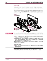
3 . Chock the wheels of the front axles to prevent vehicle movement during service .
4 . Raise the frame of the vehicle to remove the load from the suspension . Support the frame at
this height .
5 . Support the equalizing beam and remove the fasteners from the end bushing where the bar
pin alignment shim adjustment is being made .
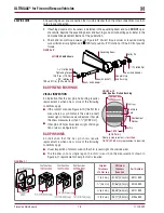
6 . Adjust shim thickness to move the axle in the desired direction, see Figure 7-6 .
EACH EQUALIZING BEAM END BUSHING HAS ONE INBOARD AND ONE OUTBOARD ALIGNMENT SHIM,
FOR A TOTAL OF FOUR SETS OF TWO ALIGNMENT SHIMS PER SUSPENSION . EACH SET OF ALIGNMENT
SHIMS FOR A PARTICULAR BEAM END BUSHING MUST BE INSTALLED IN THE SAME ORIENTATION . SHIM
ORIENTATION MAY DIFFER FOR EACH BEAM END BUSHING, SEE FIGURE 7-4 . FAILURE TO FOLLOW THESE
WARNINGS MAY RESULT IN THE FRACTURE OF EITHER THE AXLE BRACKET OR BAR PIN WHICH COULD
RESULT IN THE ADVERSE VEHICLE HANDLING AND POSSIBLE PERSONAL INJURY OR PROPERTY DAMAGE .
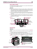
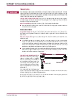
THE BAR PIN ALIGNMENT SHIM (PART NO . 50130-000) MUST BE INSTALLED WITH THE FOLDED EDGE
FACING AWAY FROM THE BUSHING, SEE FIGURE 7-7 . FAILURE TO DO SO MAY RESULT IN SHIM DAMAGE,
IMPROPER ALIGNMENT, DAMAGE OR FRACTURE OF THE AXLE BRACKET OR BAR PIN WHICH COULD
RESULT IN THE ADVERSE VEHICLE HANDLING AND POSSIBLE PERSONAL INJURY OR PROPERTY DAMAGE .
7 . Install new end bushing fasteners and tighten to:
■
At the
locknut
to 525 ± 75 foot pounds torque, or
■
At the
bolt head
to 575 ± 75 foot pounds torque


