


17730-299
31
Alignment & Adjustments
ULTIMAAX
®
for Fire and Rescue Vehicles
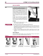
FIGURE 7-6
FIGURE 7-7
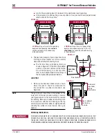
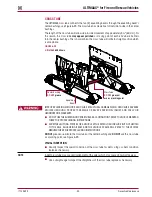
8 . Remove support and lower the vehicle .
9 . Verify the axles’ alignments are within the vehicle manufactures tolerance .
10 . Set brakes and remove wheel chocks .
Nominal
Axle Moves
Axle
Bracket
Alignment
Shim
Alignment
Shim
Alignment
Shim
Axle Moves
3 8
/ (9.5 mm)
"
3 16
/
" (4.8 mm)
Bar
Pin
Bar
Pin
Bar
Pin
3 8
/ (9.5 mm)
"
3 16
/
" (4.8 mm)
3 8
/ (9.5 mm)
"
3 16
/
" (4.8 mm)
Equalizing
Beam
Center
Equalizing
Beam
Center
Equalizing
Beam
Center
Axle
Bracket
Axle
Bracket
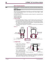
Example:
The alignment equipment shows the front drive
axle to have a 0.40° thrust angle to the left.This will
require a ¼" (6.4 mm) shim thickness increase to the
front side of the left front equalizing beam end bushing. If
there is less than ¼" (6.4 mm) of adjustment available at
this location then some of the adjustment will have to be
made at the rear of the right front end bushing. In this
case a / " (3.2 mm) shim thickness increase at the front
side of the left front bar pin
a / " (3.2 mm) shim
thickness increase at the rear side of the right front bar
pin will correct the 0.40° thrust angle.
1 8
AND
1 8
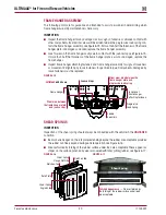
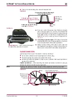
If a finer adjustment is required use alignment shim (P/N
50131-000).This alignment shim has one / " (3.2 mm) leg,
one ¼" (6.4 mm) leg, and a / " (9.5 mm) back. A total of ¾"
(19 mm) adjustment is achievable to the axle. A / " (9.5 mm)
flat shim is also available (P/N 57026-000).
1 8
3 8
3 8
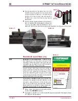
The standard alignment shims supplied with each
suspension (P/N 50130-000) have two / " (4.8 mm) legs
and a / " (9.5 mm) back. Rotating the shim pairs 90° will
change the axle alignment in ± / " (4.8 mm) increments.
3 16
3 8
3 16
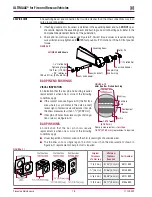
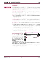
To accomplish a thrust angle adjustment rotate the
alignment shims on the bar pin of the end bushing.
Axle movement will be in the direction of the shim
thickness increase.
1 16
/ "
(1.5 mm) shim thickness increases thrust angle
by 0.10".
Axle thrust angle may be adjusted at either wheel end
on an axle. If insufficient adjustment is available at
one wheel end, the opposing wheel end will also
need to be adjusted, but in the opposite direction.
The following service notes will help when performing Hendrickson equalizing beam bar pin alignment
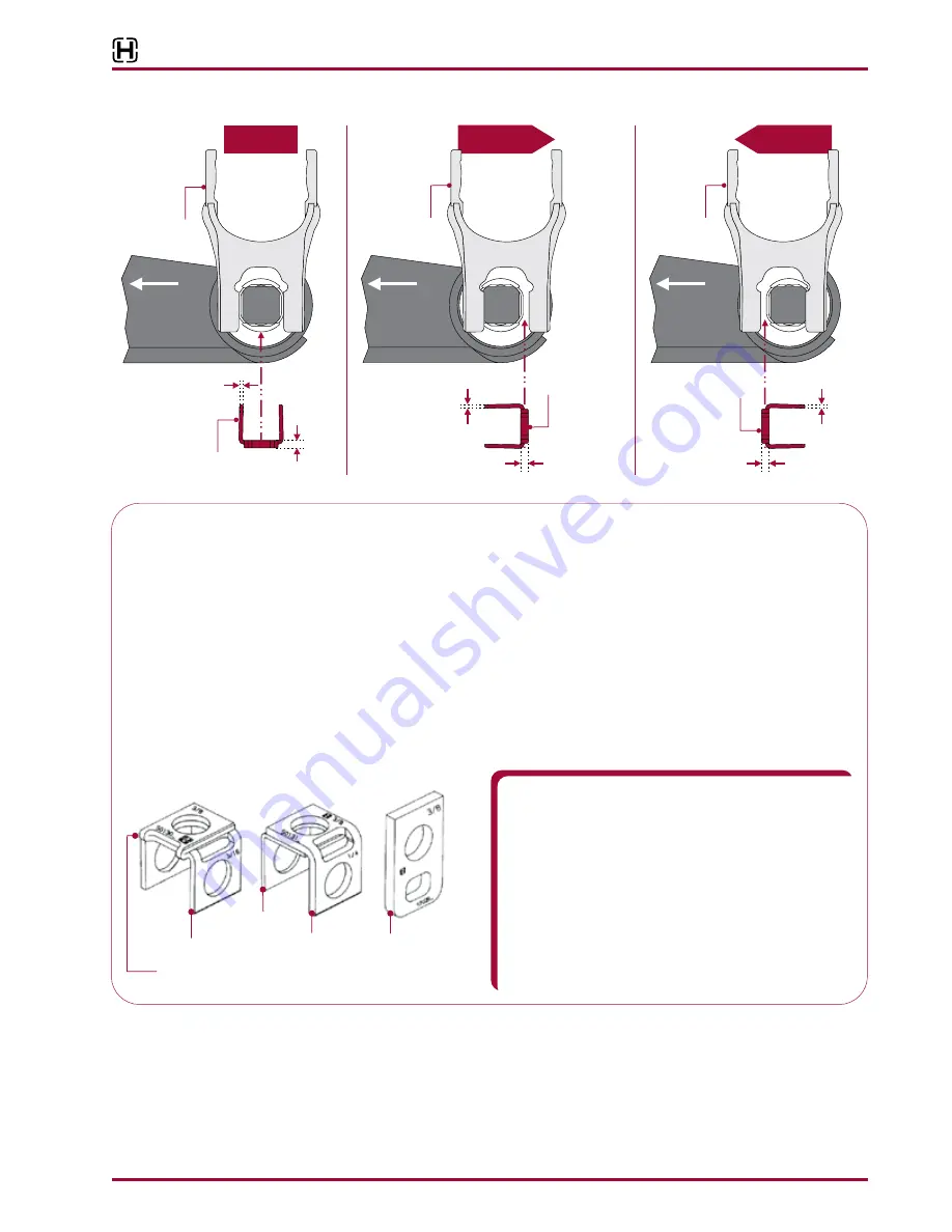
BAR PIN ALIGNMENT SHIMS
Part Number
50130-000
Part Number
50131-000
Part Number
57026-000
3 16
/
(4.8 mm) Legs
"
1 8
/ (3.2 mm) Leg
"
3 8
/ " (9.5 mm) Leg
NOTE:
Folded edge in 50130-000 shim
must be positioned away from the bushing
¼" (6.4 mm) Leg


