


17730-299
37
Component Replacement
ULTIMAAX
®
for Fire and Rescue Vehicles
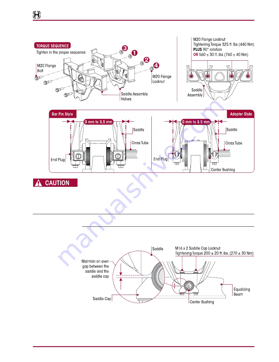
FIGURE 8-12
FIGURE 8-13
A SADDLE ASSEMBLY IS ATTACHED TO THE CENTER BUSHING OF EACH EQUALIZING BEAM WITH TWO
(2) SADDLE CAPS . EACH SADDLE CAP USES TWO (2) BOLTS TO CLAMP THE CENTER BUSHING INNER
METAL TO THE SADDLE . EACH SADDLE CAP MUST BE INSTALLED SO THAT THERE IS AN EVEN GAP
BETWEEN THE SADDLE CAP AND THE BASE OF THE SADDLE LEGS AS SHOWN IN FIGURE 8-14 . IF EACH
SADDLE CAP IS NOT INSTALLED EVENLY, THE SADDLE LEGS COULD BECOME DEFORMED, RESULTING
IN BENT BOLTS OR DAMAGED SADDLES .
NOTE
Tightening the saddle cap fasteners properly will help prevent wear of mating components, such
as the beam center bushing, saddle, and saddle cap .
16 . While tightening the saddle cap fasteners maintain an even gap between the saddle and
saddle cap, see Figure 8-14 .
FIGURE 8-14


