


6
17730-299
ULTIMAAX
®
for Fire and Rescue Vehicles
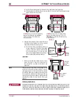
SUPPORT THE VEHICLE PRIOR TO SERVICING
PLACE THE VEHICLE ON A LEVEL FLOOR AND CHOCK THE WHEELS TO PREVENT THE VEHICLE FROM
MOVING OR ROLLING . DO NOT WORK AROUND OR UNDER A RAISED VEHICLE SUPPORTED BY ONLY
A FLOOR JACK OR OTHER LIFTING DEVICE . ALWAYS SUPPORT A RAISED VEHICLE WITH RIGID SAFETY
STANDS . FAILURE TO DO SO CAN CAUSE SERIOUS PERSONAL INJURY OR DAMAGE TO EQUIPMENT .
IMPROPER JACKING METHOD
IMPROPER JACKING METHODS CAN CAUSE STRUCTURAL DAMAGE WHICH CAN CAUSE ADVERSE
VEHICLE HANDLING, PROPERTY DAMAGE OR SEVERE PERSONAL INJURY AND WILL VOID
HENDRICKSON’S WARRANTY .
■
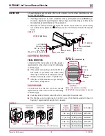
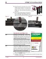
DO NOT USE THE SUSPENSION CROSS TUBE AS A JACKING POINT, SEE FIGURE 3-1, REFER TO
VEHICLE MANUFACTURER FOR PROPER JACKING INSTRUCTIONS .
■
ACCEPTABLE LIFTING POINTS FOR A VEHICLE AT THE RATED LOAD INCLUDE BUT ARE NOT
LIMITED TO: THE AXLE, EQUALIZING BEAM, AND THE VEHICLE FRAME RAIL . REFER TO THE VEHICLE
MANUFACTURER FOR PROPER JACKING INSTRUCTIONS .
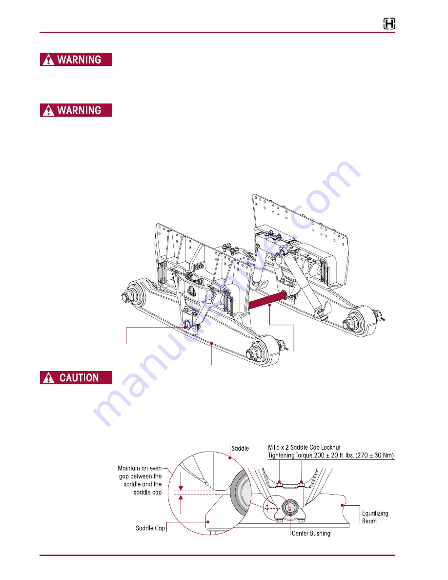
FIGURE 3-1
SADDLE CONNECTION
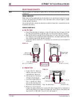
A SADDLE ASSEMBLY IS ATTACHED TO THE CENTER BUSHING OF EACH EQUALIZING BEAM WITH TWO
(2) SADDLE CAPS . EACH SADDLE CAP USES TWO (2) BOLTS TO CLAMP THE CENTER BUSHING INNER
METAL TO THE SADDLE . EACH SADDLE CAP MUST BE INSTALLED SO THAT THERE IS AN EVEN GAP
BETWEEN THE SADDLE CAP AND THE BASE OF THE SADDLE LEGS AS SHOWN IN FIGURE 3-2 . IF EACH
SADDLE CAP IS NOT INSTALLED EVENLY, THE SADDLE LEGS COULD BECOME DEFORMED, RESULTING
IN BENT BOLTS OR DAMAGED SADDLES .
FIGURE 3-2
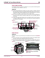
Equalizing
Beam
Center Bushing
grease
DO NOT
Cross Tube
grease or
use as a jacking point
DO NOT
63K Shown
ULTIMAAX


