17730-299
33
Component Replacement
ULTIMAAX
®
for Fire and Rescue Vehicles
SHEAR SPRING / FRAME HANGER ASSEMBLY / SADDLE ASSEMBLY
You will need:
■
Saddle Disassembly Tool
No . 66086-113L and
Saddle Assembly Tool
No . 66086-108L,
refer to the Special Tools Section of this publication .
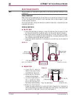
FIGURE 8-2
DISASSEMBLY
1 . Chock the front wheels of the vehicle .
2 . Raise and support the drive axles .
3 . Remove the drive tires from the side of the
vehicle being serviced .
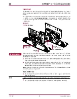
4 . Remove and discard the M16 saddle cap
fasteners that attach the saddle assembly to
the center bushing, see Figure 8-2 .
5 . Raise the vehicle’s frame just enough to create a ½" (13 mm) gap between the saddle assem-
bly and center bushing . Support the vehicle’s frame at this height .
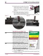
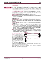
6 . Remove the progressive load springs M10 fasteners and discard, see Figure 8-4 .
7 . Remove the progressive load springs .
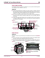
8 . Apply NLGI #2–EP (Extreme Pressure) chassis lubricant to the threaded rod of the saddle
disassembly tool, No . 66086-113L, see Figure 8-3 .
FIGURE 8-3
FIGURE 8-4
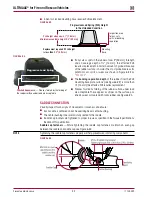
NOTE
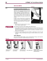
The threaded rod spacer and spacer nut are designed and orientated to fit into the saddle assem-
bly openings, see Figure 8-5 .
9 . Install both saddle disassembly tools on each end of one saddle assembly, rotate the threaded
rod blocking nuts until each are oriented properly into the saddle assembly openings, see
Figures 8-4 and 8-5 .
FIGURE 8-5
M16 Saddle Cap
Fasteners
Saddle
Saddle Cap
Center
Bushing
Saddle Disassembly Tool
Hendrickson Part No.66086-113L
Threaded
Rod Nut
Blocking
Nuts
Apply
#2–
(Extreme Pressure) chassis lubricant
NLGI
EP
Threaded Rod
Blocking Nuts
Saddle Disassembly Tool
Hendrickson Part No. 66086-113L
Saddle Assembly
Opening

