Component Replacement
38
17730-299
ULTIMAAX
®
for Fire and Rescue Vehicles
FIGURE 8-15
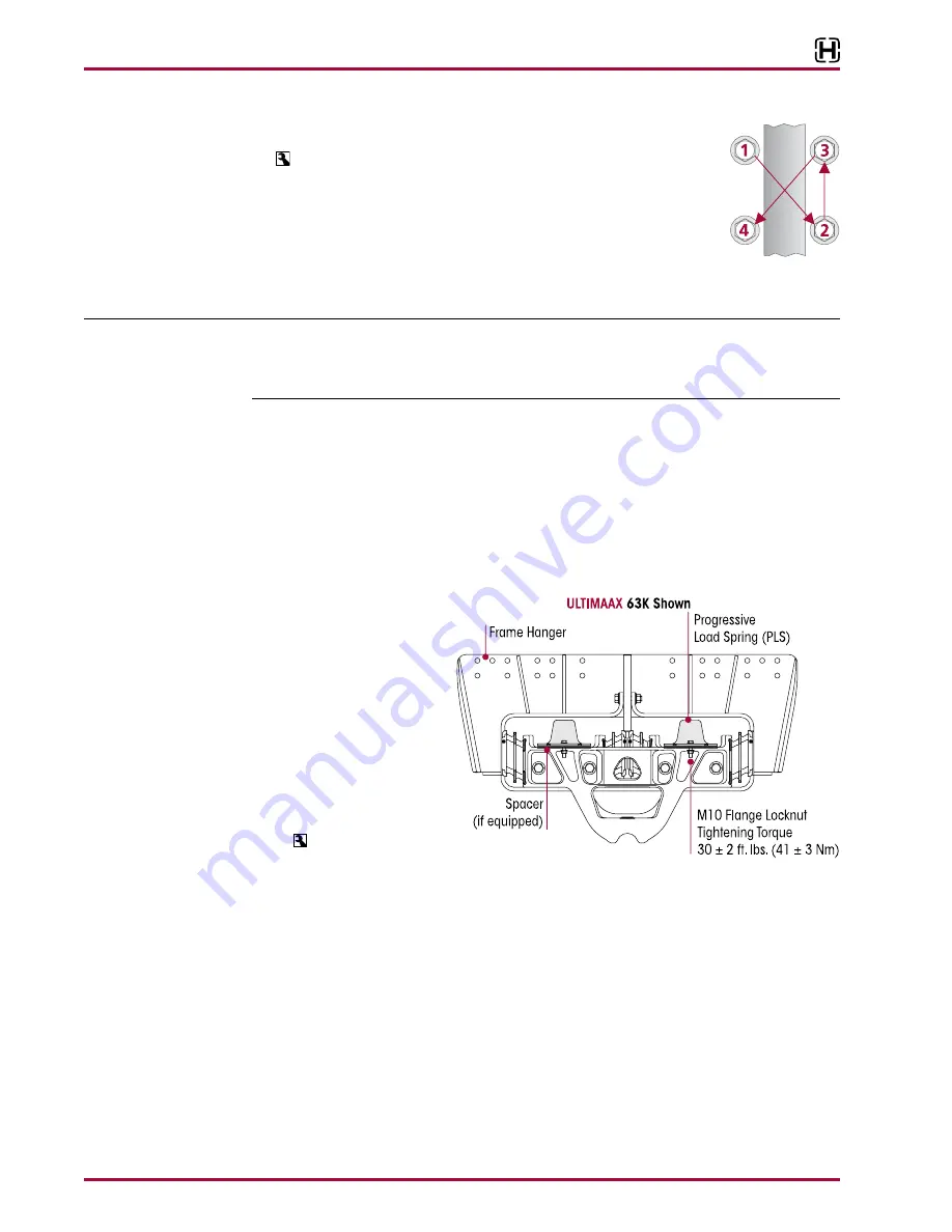
17 . Install the saddle cap fasteners and tighten evenly in several steps to
200 ± 20 foot pounds torque in proper sequence to achieve uniform
bolt tension, see Figure 8-15 .
18 . Install the tires .
19 . Remove supports from the axles and lower the vehicle onto the ground .
20 . Remove the wheel chocks .
PROGRESSIVE LOAD SPRING (PLS)
NOTE
The Hendrickson ULTIMAAX suspension progressive load springs must be replaced in pairs (left
side pairs or right side pairs or rear position pairs or front position pairs), even if only one PLS
shows unacceptable conditions . Replacement of only one PLS can cause uneven wear, and
higher premature wear for the one replaced .
DISASSEMBLY
1 . Chock the front wheels of the vehicle .
2 . Raise the vehicle’s frame until the saddle assembly contacts the bottom of the frame hanger
assembly . Support the vehicle’s frame at this height with safety stands .
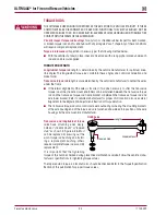
3 . Remove and discard the four M10 flange bolts that attach the progressive load springs to the
saddle assembly, see Figure 8-16 .
4 . Remove the PLS from the frame hanger assembly .
FIGURE 8-16
ASSEMBLY
1 . Install the PLS into the
frame hanger assembly .
2 . Install the four M10 flange
bolts that attach the PLS
to the saddle assembly .
The flange bolts
must
be
installed with the lock-
nuts facing downward as
shown in Figure 8-16 .
3 . Tighten the PLS fasteners
to 30 ± 2 foot pounds
torque .
4 . Remove the frame safety stands and lower the vehicle .
5 . Remove the wheel chocks .
EQUALIZING BEAM
DISASSEMBLY
1 . Chock the wheels of the steer axle .
2 . Raise and support the drive axles with safety stands .
3 . Remove the tires .
4 . Support the pinion angle of the drive axles to prevent axle movement during service .
5 . Remove the saddle cap bolts from both inboard and outboard sides of the equalizing beam .
6 . Remove the saddle caps, see Figure 8-17 .


