Pressure Transmitters 050D series
Operating Instructions
- English - V1.0
PN-TI118-EN-14-1/13
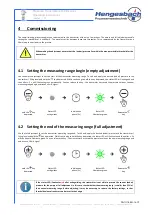
Hengesbach GmbH & Co. KG
·
Schimmelbuschstr. 17
·
40699 Erkrath
·
Tel. +49 (0) 21 04 / 30 32-0
·
Fax +49 (0) 21 04 / 30 32-22
·
www.hengesbach.com
9.3
Connection diagram for normal measuring mode
The electrical connection of the device is made via the connection terminals in the housing head. A device with an integrated M12 device
connector or a permanently connected reference cable does not require any alterations - the connections of connection terminals with the
pin allocation specified on the type plate has been made in the factory. The reference cable wires are coloured according to their function
and are already wired in accordance with the type plate upon delivery.
If your device is equipped with a cable screw connection, you will need to connect the device yourself. To do so, unscrew the device lid in
an anti-clockwise direction - this could require a little strength as the seal is guaranteed only by a secure lid.
After removing the device lid, you have access to the connection terminals. The electrical connection for normal measuring operation is
performed according to the following schematic:
Connect the power supply with the transmitter via the terminals
1 (+)
and
2 (-)
Observe and comply with the permissible voltage range of
12…30V DC. Ensure maintenance of the correct polarity - the voltage reversal does not cause any damage, but it will not commence
measurement operation. The pressure value determined by the transmitter is depicted in the supply loop with a current proportional to
the process pressure from 4…20mA . This value can be determined by a looped-in current measuring device.
The loop current can be checked on the device via the
TE
and
ST
terminals without needing to separate the supply loop. To this end,
connect a hand-held multimeter or similar current measuring device to the terminals. TE represents the positive and ST the negative
connections.
A potential equalisation can be established with the connected control via the connection marked with an earthing symbol. If the
transmitter housing does not have a connection with sufficient conductance, we recommend using this connection.
Use shielded wires for the electrical connection and ensure that the shield is connected to the housing conductively. This can either be
performed via the cable screw connection or a suitable M12 device connector.
The slide switch must be in the N position (delivery state) for normal measuring mode.
4…20
mA
4…20
mA
I
I
Position N
Earth


