Pressure Transmitters 050D series
Operating Instructions
- English - V1.0
PN-TI118-EN-14-1/14
Hengesbach GmbH & Co. KG
·
Schimmelbuschstr. 17
·
40699 Erkrath
·
Tel. +49 (0) 21 04 / 30 32-0
·
Fax +49 (0) 21 04 / 30 32-22
·
www.hengesbach.com
9.4
Calibration function with external process calibrator
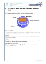
In order to be able to use the calibrator function with a mobile process calibrator, use a small screwdriver or similar instrument to bring
the slide switch in position
C
. The electrical connection of the process calibrator is performed via the terminals
TE
and
ST
. TE represents
the positive (+), ST the negative (-) poles of the supply.
Ensure that the instrument used to calibrate the power supply has its own power supply located within the
specified thresholds between 12…30V DC. It must be able to provide a minimum current of 22mA.
In this configuration, the transmitter is supplied by a mobile instrument and depicts its measured value through a proportional current in
the calibrator loop. The supply via the terminals 1 and 2 is not in operation - it need not be disconnected.
The slide switch does not establish a galvanic isolation between the two circuits. The calibration function is
designed for the use of mobile process calibrators alone. Given other applications, ensure a galvanic isolation of
the supply.
Whilst the slide switch is in position C, a signal is not issued via the normal power supply on terminals 1 and 2.
Ensure that this does not lead to any malfunctions in the control.
The following figure shows the electrical connection of a mobile process calibrator:
Ensure that the slide switch is returned to the N position after successful calibration otherwise the device will not issue an output signal.
+
–
Position C
I
4…20
mA


