background image


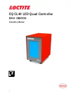
EQ CL40 LED Quad Controller 

IDH# 2804936


Operating Manual 


Summary of Contents for 2804936

Page 1: ...1 EQ CL40 LED Quad Controller IDH 2804936 Operating Manual ...

Page 2: ...Display operating elements and connections 7 3 Technical Data 8 4 Installation 9 4 1 Environmental and Operating Conditions 9 4 2 Connecting the Unit 9 5 Operation 9 5 1 Electrical Connection 9 5 2 Turn on the Unit 9 5 3 Main Page 10 5 4 Parameter Setting Page 11 5 5 Control Operation Page 14 6 Application Hints 14 7 Troubleshooting 14 8 Care and Maintenance 16 9 Accessories and Spare Parts 16 10 ...

Page 3: ...r Your Safety For safe and successful operation of the unit read these instructions completely If the instructions are not observed the manufacturer can assume no responsibility Do not expose the connecting cable to heat oil or sharp edges Make sure the Unit stands stable and secure Use only original equipment replacement parts Always disconnect the power supply before servicing the unit Observe g...

Page 4: ...ce Doing so could cause eye damage Install the LED head in a way that individuals are not exposed to LED UV light Exposure could injure the skin or cause other injury If there is a risk of the LED UV light being exposed to persons place the product inside a cover with proper reflectance and heat characteristics to block that reflected light When operating the controller set up the system so that t...

Page 5: ...uld be reported to the manufacturer 1 4 Packing List 1 4 1 EQ CL40 LED Quad Controller x 1 1 4 2 Equipment Manual x 1 1 4 3 Power Cord x 1 1 4 4 Footswitch x 1 1 4 5 Footswitch Adapter x 1 1 5 Features 1 5 1 Capacity for up to four UV LED Heads 1 5 2 Works with Loctite EQ CL40 Spot Heads 1 5 3 Touch screen HMI 1 5 4 3 running modes Timer Continue and Advance 1 5 5 User friendly interface 1 6 Usage...

Page 6: ...the cure cycle is initiated light is immediately irradiated at or near maximum intensity from the LED s The curing process begins when the adhesive is placed under the LED s The two primary variables that control the curing process are the time of exposure and the strength of the light irradiance For a given irradiance the exposure time required to fully cure the adhesive depends primarily on the ...

Page 7: ...7 2 2 Display operating elements and connections 1 Power Supply Inlet 2 Power Switch ON OFF 3 Head Connection 4 PLC IO Interface 5 Socket XS5 RS232 6 Screen ...

Page 8: ...Dimensions W x H x D 99x162x163 mm Total weight Kg lbs 2 4 4 Operating voltage 24V DC 60W Adapter Power consumption 35 Watts Operating Temperature 10 C to 40 C 50 F to 104 F Storage Temperature 10 C to 60 C 14 F to 140 F ...

Page 9: ...roller to the PLC interface or the footswitch adapter Connect the LED head s connector to the 6 pins connector Connect power cord to the appropriate plug 5 Operation 5 1 Electrical Connection Plug the end of the LED power cable into the 6 pins connector located on the rear panel of the CL40 controller Make sure that the connection is secure Plug the DC power cord into the back of the controller an...

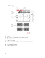
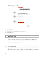
Page 10: ...tch 2 Channel 3 LED head running Mode CONTINUE TIMER ADVANCE 4 Intensity percentage 5 Time Exposure time 6 Temperature To display LED head temperature For indication only 7 To Main page 8 To Parameter Setting page 9 To Warning Message page ...

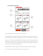
Page 11: ...er Mode The LED head will turn ON when a footswitch is pressed and remain ON for the duration that is set on the timer If the time is set to 0 then when a footswitch is pressed the LED head will turn ON and remain ON until the Footswitch is pressed again The intensity can be set up for each channel independently Advance Mode This enables intensity to change automatically during the curing cycle 2 ...

Page 12: ...Timer setting When clicked can enter below page to set intensity and timer Continue Mode Enter required intensity percentage setting normal operation set 100 Timer Mode Enter required intensity percentage setting normal operation set 100 and curing time required Continue ...

Page 13: ...les intensity to change automatically during the curing cycle For example if operator have defined as below when start signal comes LED head will work step by step Time and power will follow each step s setting to run 2 cycles ...

Page 14: ... Hints As with all adhesives performance depends on conditions of use Suggestions or recommendations contained herein are for guidance only since actual conditions of use are outside the supplier s control 7 Troubleshooting Before proceeding with any repair or maintenance operation disconnect the tool from the main electricity supply ...

Page 15: ...D head temperature has reached the warning level If you continue the operation in this condition the product life will be significantly shortened and the temperature may exceed the upper limit 650 C causing an emergency stop Set the UV intensity level lower or improve the heat radiation performance of the LED head to keep the temperature lower than the warning level Check if the fan on the LED hea...

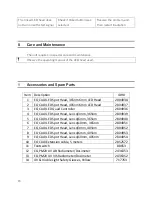
Page 16: ...40 LED Spot Head 405nm 6mm LED Head 2804937 3 EQ CL40 LED Quad Controller 2804936 4 EQ CL40 LED Spot Head Lens φ3mm 365nm 2804939 5 EQ CL40 LED Spot Head Lens φ6mm 365nm 2804940 6 EQ CL40 LED Spot Head Lens φ10mm 365nm 2804951 7 EQ CL40 LED Spot Head Lens φ3mm 405nm 2804952 8 EQ CL40 LED Spot Head Lens φ6mm 405nm 2804953 9 EQ CL40 LED Spot Head Lens φ10mm 405nm 2804954 10 EQ CL40 Extension cable 5...

Page 17: ...17 10 Diagrams PLC IO Interface ...

Page 18: ...rishable items such as fuses filters lights etc No such claim shall be allowed in respect of products which have been neglected or improperly stored transported handled installed connected operated used or maintained In the event of unauthorized modification of the Products including where products parts or attachments for use in connection with the Products are available from Henkel the use of pr...

Page 19: ...SSIBLE UNDER APPLICABLE LAWS HENKEL EXPRESSLY DISCLAIMS ANY LIABILITY WHATSOEVER FOR ANY DAMAGES INCURRED DIRECTLY OR INDIRECTLY IN CONNECTION WITH THE SALE OR USE OF OR OTHERWISE IN CONNECTION WITH THE PRODUCTS INCLUDING WITHOUT LIMITATION LOSS OF PROFITS AND SPECIAL INDIRECT OR CONSEQUENTIAL DAMAGES WHETHER CAUSED BY NEGLIGENCE FROM HENKEL OR OTHERWISE 12 Declaration of Conformity 04 36 CL40 LED...

Page 20: ...Par Technocentre SINGAPORE 149598 Henkel China Company Ltd No 928 Zhang Heng Road Zhangjiang Hi Tech Park Pudong Shanghai China 201203 Henkel Loctite Korea 8F Mapo Tower 418 Mapo dong Mapo gu Seoul 121 734 KOREA Henkel Japan Ltd 27 7 Shin Isogo cho Isogo ku Yokohama 235 0017 JAPAN Henkel AG Co KGaA Henkelstraße 67 40191 Düsseldorf Deutchland www equipment loctite com and designate trademarks of He...

Reviews: