background image

Operating Manual

Lineguard 97 MeasCon

Control and Monitoring Unit

Summary of Contents for Lineguard 97 MeasCon

Page 1: ...Operating Manual Lineguard 97 MeasCon Control and Monitoring Unit ...

Page 2: ...outputs 6 1 5 3 LCD Display with push button operation 7 1 5 4 Password protection 7 1 5 5 Corrosion resistant NEMA12 Enclosure 7 2 Description 8 2 1 Product Benefits 8 2 2 Unit Structure 8 2 3 Exploded View 9 2 4 Installing Modules Initial Configuration 10 3 Technical Data 13 3 1 Basic Lineguard 97 Controller 13 3 2 pH measuring 13 3 3 ORP Redox Measuring 13 3 4 Temperature Measuring 14 3 5 Condu...

Page 3: ...duleOutputs 19 4 7 Sensor Information and Connections 19 4 7 1 Sensor Immersion Installation Requirements 20 4 8 Start up 20 4 8 1 Typical Start Up for measurement type 21 4 8 2 Configuration 21 4 8 3 Configuration Error 21 4 8 4 Configuration Menu 22 4 8 5 Initiation 22 4 8 6 Measurement Screen 22 5 Operation 23 5 1 General notes for Operation 23 5 2 Operating Flow Chart 23 5 3 Operating Level 24...

Page 4: ... 7 1 7 1 Reset Option Menu 32 7 1 8 Adoption of Standard Values for Measuring Module X 32 7 1 9 Multiple pH Measurement 32 7 1 9 1 System Configuration PAGE 1 32 8 Troubleshooting 33 8 1 Display Blank After Turning ON Power 33 8 2 Configuration Error After Turning ON Power 33 8 3 Display Value Remains Zero Despite Altered Conductivity Value 33 8 4 Display Value Unstable 33 8 5 Error Message Plausi...

Page 5: ... Maintenance 35 9 1 Sensor Module Service 35 9 2 Setting the Display Contrast 35 9 3 Replacing the Main Power Fuse F1 35 9 4 Replacing a Module 35 9 5 Replacing the Door 36 9 6 Replacing the Base Board 36 10 Accessories and Spare Components 37 10 1 Accessories 37 10 2 Measurement Modules 37 11 LG97 Wiring Diagram 38 12 Warranty 39 ...

Page 6: ...riginal equipment replacement parts Always disconnect the power supply before servicing the unit Observe general safety regulations for the handling of chemicals such as Bonderite products Observe the manufacturer s instructions as stated in the Safety Data Sheet While under warranty the unit may be repaired only by an authorized Henkel service representative 1 3 Unpacking and Inspection Carefully...

Page 7: ...Operating Manual Page 7 1 5 3 LCD Display with push button operation 1 5 4 Password protection 1 5 5 Corrosion resistant NEMA12 Enclosure ...

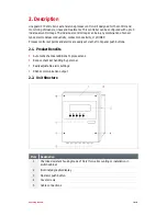
Page 8: ...ctrodeless conductivity contact conductivity or pH ORP Process control set points and alarms are easily set via the front panel push buttons 2 1 Product Benefits Automatic chemical additions to process tank Reduce chemical handling by personal Easily adjustable alarm settings RS232 communication output 2 2 Unit Structure Item Designation 1 Chemical resistant housing made of Noryl for wall mounting...

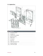
Page 9: ...ed View Item Designation 1 Housing lower section 2 Housing cover 3 Processor board with EPROM 4 Base Mother board 5 Retainer band 6 Cover screws 7 Relay board 8 Measuring control modules 9 PU screw connections 10 Plug for relay outputs ...

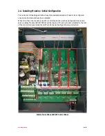
Page 10: ... all control modules have been installed When more than one module is used for controlling devices such as pumps and or solenoid valves a Relay Module IDH 1739319 will be required The relay module is located to the left of the control modules inside the LG97 control panel See Figure below and section Inside View of Base LG97 47 Control Panel Pin Sockets Motherboard ...

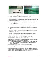
Page 11: ...one stand off and one plastic screw to secure it into place If there is only one control module installed the module will need to be installed in Module 1 location There always needs to be a module installed in this location for proper operation of controller Additional modules can be installed in the remaining locations as required Install the standoff into the treaded hole on the motherboard Whe...

Page 12: ...ositive for chemical control Negative for rinse control Positive for chemical control Negative for alkali Control Positive for acid Control Positive for Autophore tic chemical control Switch Difference XSD Dead band at Control Point 1 as of set point W 0 0 0 0 0 0 0 0 Switch Delay Time ON Output switched ON n seconds after signal drops below set point W if control is Positive Output switched ON n ...

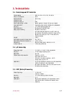
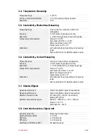
Page 13: ...eight 2 5 kg Permissible operation temperature 0 to 45 C Permissible storage temperature 20 to 60 C Dimensions 224 mm 8 818 inches 290 mm 11 417 inches 95 mm 3 700 inches W D H 3 2 pH measuring Measuring range 0 14 pH 2 12 pH 3 8 pH adjustable Accuracy 1 of measuring range end Resolution 0 01 pH Temperature compensation Manual 0 100 C Automatic with Pt 100 2 3 wire connection possible 0 100 C Temp...

Page 14: ...S configurable Accuracy 1 of measuring range end value Resolution 1 0 001 µS depending on measuring range Temperature compensation Manual 0 100 C Automatic with PF100 0 100 C Reference temperature 25 C Temperature unit C or F Calibration with calibration box depending on measuring range Auto read function for stable measured value 3 7 Standard Signal Signal input terminal 1 0 4 20 mA Option galvan...

Page 15: ...Operating Manual Page 15 Switch difference X2SD 0 30 0 3 9 Limit Contact Limit contact L Measuring module range Limit contact L Measuring module range Switch difference X2SD 0 30 0 ...

Page 16: ...4 cover screws Use the housing as a template and scribe the 4 mounting holes onto the surface where the controller will be mounted Drill the scribe marks using a 6 mm 1 4 drill bit Insert dowel plugs supplied with the controller Attach housing using the screws provided Close the housing and tighten the 4 cover screws When Closing the housing ensure that the seal is not damaged and it is seated exa...

Page 17: ...Operating Manual Page 17 4 4 Dimensions E CO Lineguard 97 Controller Wall MountingHoles 4 5 Base Board Main Mother Board 4 5 1 Terminal Connection Diagram ...

Page 18: ...ional relay module must be installed See Section 4 6 4 5 2 3 Current Outputs Module No SignalDescription Terminal Position 1 Measurement control Module 1 7 8 2 Measurement control Module 2 9 10 3 Measurement control Module 3 11 12 When Connecting the power outputs pay careful attention to the correct polarity and the maximum load 600 4 5 2 4 Serial Output This port is for Henkel use only NO access...

Page 19: ... 7 NOT USED 26 27 Normally Open 26 27a Normally Closed All E CO Lineguard 97 relay connections have a spark quenching circuit through which a minimal residual current can flow even if the contact is open 4 7 Sensor Information and Connections Module Sensor Wiring 1598683 Meas Module Conductivity ind 689734 Sensor Electrodeless Conductivity 1598685 Meas Module Conductivity cond 1997904 Sensor Conta...

Page 20: ...ief Tie the excess sensor cable into a loose loop with plastic cable ties and attach to any convenient cool piping or brackets to hold the cable out of the way of maintenance activity on the tank Never cut or modify the sensor cable Attach the cable wires to the respective function module using the wiring diagrams shown in the section 4 7 1 Sensor Electrical Connections to Each Style If required c...

Page 21: ...sired values for High alarm L and Low alarm L Typically alarms are set to 1 uS from the set point pH Insert the sensor into the bath and adjust the set point to the desired pH value Adjust the alarm limits to the desired High alarm L and Low alarm L Typically alarms are set to 2 pH from the set point ORP Insert the sensor into the bath and adjust the set point to the desired value Adjust the alarm...

Page 22: ... 6 Choose operator level from the menu to return to the initial menu for the controller 4 8 5 Initiation Once the operation voltage has been applied the MeasCon 97 logo with the program version is displayed for 5 seconds 4 8 6 Measurement Screen Example when equipped with two measuring modules Once 5 seconds have elapsed the unit switches to the operating level and the measurement screen appears e...

Page 23: ...which point the corresponding arrow key is released is the one that remains The value is adopted through operating the ENTER key The key is used to cancel the respective setting If set values have changed these are saved during the change to the operating level measurement screen Only the changed values are adopted All the controllers are turned off when adjusting the values in the configuration m...

Page 24: ...enu The main menu for the adjustment of the MeasCon 97 is opened through operating the key in the measurement mask screen 5 5 2 Measurement Parameter Settings Adjustment of the module specific measurement parameters For a more detailed description see Measurement Parameters in the supplement manual of the relevant measurement module 5 5 3 Controller Parameter Settings Adjustment of the module spec...

Page 25: ...module 3 Individual setting means that every module carries out its own temperature measurement for the respective temperature compensation of the measured value comparative pH setting made for pH measurement is responsible for self monitoring pH measurements value range no comparison 2 comparisons 3 comparisons The pH module on plug in connection 1 must have a controller identifier since only the...

Page 26: ...he format of the date is month day year in two digits After confirmation the date time it lasts about 2 sec to take over the setting After takeover of the date time the input cursor will be positioned on the date time selection Value ranges Date 01 01 00 to 12 31 99 Time 00 00 to 23 59 Initial operation change or repositioning of measurement control modules will require system configuration config...

Page 27: ...vated via the ENTER key or until the cursor is placed on the relay output selection To inspect the current outputs the corresponding current output number in the current output line must be selected The maximum output current of this current output is switched through operating the ENTER key It remains activated as long as the ENTER key is operated The minimum current of this current output can al...

Page 28: ...to enter a hysteresis 6 3 Parameters Setpoint Set point W Set point value lies within the measuring range including switching point 1 Switch difference XSd Switching hysteresis around the set point value the percentage relates to the set point value Note Not used see Switch Delay Times Set point difference LW Distance between switching point 2 and the set point value Given in positive and negative...

Page 29: ...ues In addition to this the switching points are assigned a hysteresis characteristic which itself are independent of the control 6 6 Parameters Limit Limit contact L Lower alarm limit adjustable as an absolute value within the measuring range Limit contact L Upper alarm limit adjustable as an absolute value within the measuring range It is essential to ensure that L is adjusted smaller than L Swi...

Page 30: ...at has been assigned is automatically displayed This access code can be changed The values of the respective positions can be changed with the keys The position that is to be changed can be accessed with the cursor through operating the keys Once the set access code has been adopted through operating ENTER the system configuration menu is displayed again 7 1 3 Protective Mechanism Every setting me...

Page 31: ...ed with access codes per the same principle A calibration cannot be carried out without an access code 7 1 6 Use of Master Code If access protection is cancelled using the master code this lack of protection is indicated by a key and explanation mark in the last row of the display screen The lack of protection icon can only be removed by confirming the original access code 7 1 7 Reset Performing a...

Page 32: ...suring Module X The MeasCon 97 logo appears after a short period and operating can commence again The MeasCon 97 restarts once the saving process is completed To trigger only one restart of the MeasCon 97 while operating warm start the menu item system in the reset options must be operated 7 1 9 Multiple pH Measurement This option is not utilized with this controller and this configuration 7 1 9 1...

Page 33: ...ctive 8 2 Configuration Error After Turning ON Power POSSIBLE CAUSE REPAIR Existing modules and configuration do not match Check configuration and modules Press to reconfigure 8 3 Display Value Remains Zero Despite Altered Conductivity Value POSSIBLE CAUSE REPAIR Conductivity cable connection to sensor not correct or broken Inspect cables and establish connection 8 4 Display Value Unstable POSSIBL...

Page 34: ... CAUSE REPAIR Signal output circuit 4 20 mA Check signal output for ground loops 8 9 Display Remains Constant Despite Altered pH Value POSSIBLE CAUSE REPAIR If pH 7 short circuit in electrode lead or moisture trapped in the plug in connections Inspect Electrode connectors and cable for moisture Replace if necessary If pH 5 and unchanging glass electrode may be broken Replace glass pH electrode 8 1...

Page 35: ...d The Unit is connected to power Loosen the 4 cover screws and open the housing Adjust contrast potentiometer P1 on the display board Close and fasten housing cover For following operations the power must be disconnected from the unit Strictly follow all safety requirements 9 3 Replacing the Main Power Fuse F1 The main power fuse F1 is located on the mother board left side above the power terminal...

Page 36: ...ap Plug in the ribbon cable to the main board Replace the relay board make sure the pins line up and insert with socket positions Insert and tighten the relay board fastening screws Close and fasten housing cover Connect power Perform configuration parameter assignment and calibration steps as needed 9 6 Replacing the Base Board Disconnect power Loosen the 4 cover screws and open the housing Remov...

Page 37: ...cable mt 15 689734 Sensor Electrodeless Conductivity 2028843 ORP Redox Combination Electrode 1598682 Conductivity probe PVC f f 2028841 Temperature sensor Pt 100 694708 Flow probe P P 1786902 Contact cond immersion probe 10 2 Measurement Modules Part No Description 1598685 Meas Module Conductivity cond 1598683 Meas Module Conductivity ind 1598684 Meas Module pH 1598681 Meas Probe 0 10pH HF res 202...

Page 38: ...Operating Manual Page 38 11 LG97 Wiring Diagram ...

Page 39: ... modification of the Products including where products parts or attachments for use in connection with the Products are available from Henkel the use of products parts or attachments which are not manufactured by Henkel no claim shall be allowed No Products shall be returned to Henkel for any reason without prior written approval from Henkel Products shall be returned freight prepaid in accordance...

Reviews: