3
Diagrams of Common Valves and Parts
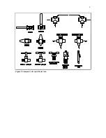
The below diagrams depict common 2-way and 3-way ball valves and the handle styles are likely
to be encountered on this machine. Also, shown in the following diagrams are miscellaneous parts
likely to be used by this machine. These diagrams are for reference only and may not show all
types and styles of ball valves and other parts.
The 2-way ball valves are shown in the OPENED and CLOSED positions. The 3-way ball valves
are shown in both flow direction conditions (see arrows). In some cases, a 3-way ball valve may
be adjusted to a NEUTRAL position, 90 degrees from the positions shown below. These
NEUTRAL positions may or may not stop flow through the valves and should not be used as
operating positions unless specified elsewhere in this manual. In some cases this machine may
contain a 3-way diverted ball valve which will appear identical to the 3-way ball valves shown
below. In the case of a diverted ball valve, the handle only turns 90 degrees (not 180 degrees) and
there is no NEUTRAL position.
Figure 1-Common Ball Valves


