background image

ITM/I718-

R

R

R

O

D

R

H

H

K

F

14

15

15

15

16

17

PASSO 10

14

FRENTE DE GAVETA

x3

15

LADO DE GAVETA

x6

D

03

F

06

K

06

O

03

R

24

V

PEÇAS REQUERIDAS

FERRAMENTAS NECESSÁRIAS

ACESSÓRIOS REQUERIDOS

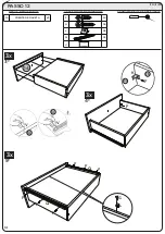
PASSO 11

15

LADO DE GAVETA

x6

16

FUNDO DE GAVETA

x3

17

RIPA DE TRÁS

x3

H

06

V

PEÇAS REQUERIDAS

FERRAMENTAS NECESSÁRIAS

ACESSÓRIOS REQUERIDOS

3x

3x

F

R

V

K

15

 Cantoneira próximo da 

borda do lado de gaveta 

(15)

Soporte en ángulo cerca 

del borde del lado del 

cajón (15)

Angle bracket near edge 

of drawer side (15)

V

13

ITM/I718-

V

15

17

Summary of Contents for I123-165

Page 1: ...oducto O sistema de montagem dos produtos funciona de acordo com a ordem crescente dos n meros indicados no desenho Ex 01 02 03 04 at a conclus o da montagem El sistema de montaje de los productos fun...

Page 2: ...ACESS RIOS ACCESORIOS ACCESSORIES 1 1 Parafusos em escala Tornillos escalados Scaled screws ITM I123 x1 x38 x7 x4 x4 x68 x58 x10 x73 x18 x4 x29 x5 x4 x2 A F K L M N O G H I J B C D E 2...

Page 3: ...ACESS RIOS ACCESORIOS ACCESSORIES ITM I123 x4 x9 x9 x5 x2 x2 x1 x30 x3 x1 x1 x1 x1 x1 x1 R U W X Y Z AA AB AC AD AE V S T Q x8 P 3...

Page 4: ...A TAPA SMALL TOP 563 445 15 13 2 2 01 TAMPO MAIOR TOP M S GRANDE TOP BIGGER 791 445 15 14 1 2 01 MOLDURA LATERAL ESQUERDA MARCO DEL LADO IZQUIERDO LEFT SIDE FRAME 1667 60 15 15 1 2 01 MOLDURA LATERAL...

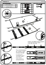
Page 5: ...K H H H L L L L L M M M M M M M M M 1 2 3 2 3 3 1 1 2 3 1 5 PASSO 1 1 RODAP FRONTAL x1 2 TRAVESSA DO RODAP x1 3 RODAP TRASEIRO x1 F 02 H 02 K 02 L 04 M 08 O 02 PE AS REQUERIDAS FERRAMENTAS NECESS RIA...

Page 6: ...je de la diapositiva siga las instrucci n en el lado For disassembly of the slide follow the instruction on the side ITM I123 4 5 6 R R U U U U G G G G G GG X X X X H H H P P P F F F F FF F F 4 6 5 4...

Page 7: ...7 8 9 R R U U U U G G G G G G G X X X X F F F F F F FF 7 7 7 7 M M M M M M M M M M M 8 9 7 7 F 06 G 08 M 14 R 01 U 03 X 02 FERRAMENTAS NECESS RIAS ACESS RIOS REQUERIDOS PASSO 3 PE AS REQUERIDAS 7 DIV...

Page 8: ...TM I123 10 11 M M M M M F 06 H 02 M 04 P 02 U 03 U U U U F F F F FF FF 11 H H H P P P 11 10 11 8 PASSO 4 10 TAMPO x1 11 LATERAL DIREITA x1 PE AS REQUERIDAS FERRAMENTAS NECESS RIAS ACESS RIOS REQUERIDO...

Page 9: ...ITM I123 3 2 1 F 3 1 2 F F F 02 9 PASSO 5 PE AS REQUERIDAS FERRAMENTAS NECESS RIAS ACESS RIOS REQUERIDOS 1 RODAP FRONTAL x1 2 TRAVESSA DO RODAP x1 3 RODAP TRASEIRO x1...

Page 10: ...ITM I123 6 4 5 B B C C C 10 PASSO 6 B 02 C 03 PE AS REQUERIDAS FERRAMENTAS NECESS RIAS ACESS RIOS REQUERIDOS 4 LATERAL ESQUERDA x1 5 PRATELEIRA MAIOR x1 6 TAMPO DAS GAVETAS x1...

Page 11: ...ITM I123 10 7 8 8 9 C C C C C C C C C C 11 PASSO 7 7 DIVIS O x1 8 PRATELEIRA x2 9 BASE x1 10 TAMPO x1 C 10 PE AS REQUERIDAS FERRAMENTAS NECESS RIAS ACESS RIOS REQUERIDOS...

Page 12: ...K 11 4 7 R Z Z 19 19 Y Y J I I I I I I I I I I I I I I I I I I I I I I I 19 19 19 12 PASSO 8 PE AS REQUERIDAS FERRAMENTAS NECESS RIAS ACESS RIOS REQUERIDOS 11 LATERAL DIREITA x1 19 FUNDO X3 B 02 C 06...

Page 13: ...16 y 17 estaban a 20 mm dentro de los bordes de las tapas 12 y 13 Frames 16 and 17 were 20mm inside the edges of the tops 12 and 13 13 PASSO 9 12 TAMPO MENOR x1 13 TAMPO MAIOR x1 16 MOLDURA SUPERIOR...

Page 14: ...atornille el marco lateral 14 y 15 2mm sobre el borde frontal del lado alineado con l La medida desde el borde hasta el marco debe ser de 58 mm After placing the roof screw the side frame 14 and 15 2m...

Page 15: ...ro das bordas do tampo 12 e 13 La parte inferior 18 debe colocarse 3mm dentro de los bordes superiores 12 y 13 Bottom 18 should be placed 3mm inside the top edges 12 and 13 15 PASSO 11 18 FUNDO SUPERI...

Page 16: ...0 20 20 21 21 20 20 4 7 11 21 21 D T D T T U T T T T T T S F F FF F F F F F F F F F F 16 PASSO 12 20 PORTA MEMOR x2 21 PORTA x1 PE AS REQUERIDAS FERRAMENTAS NECESS RIAS ACESS RIOS REQUERIDOS D 03 F 18...

Page 17: ...3 2x 1 2 2x 2x 4x 2x H H G D G S K M M M M M G K AC AC AC 17 PASSO 13 22 FRENTE DE GAVETA x2 23 LADO DE GAVETA x4 24 FUNDO DE GAVETA x2 25 RIPA DE TRAS x2 PE AS REQUERIDAS FERRAMENTAS NECESS RIAS ACES...

Page 18: ...n del producto en la pared la no colocaci n de estos herrajes para fijaci n A F V y W podr permitir que el El producto se vuelve causando accidente Indispensable to fix the product on the wall not the...

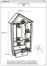
Page 19: ...19 PASSO 16 ACESS RIOS REQUERIDOS Pesos m ximos recomendados com carga distribu da Peso m ximo recomendado con la carga distribuida Recommended maximum weight with distributed load 2000 mm 1090 mm 45...

Page 20: ...ITM I123 20 Rev 000 Produto Conclu do Producto terminado Finished Product...

Page 21: ...puedan da ar su producto O sistema de montagem dos produtos funciona de acordo com a ordem crescente dos n meros indicados no desenho Ex 01 02 03 04 at a conclus o da montagem El sistema de montaje de...

Page 22: ...ACESS RIOS ACCESORIOS ACCESSORIES 1 1 Parafusos em escala Tornillos escalados Scaled screws ITM I718 x1 x48 x8 x6 x2 x6 x6 x39 x10 x5 x19 x4 x14 A F K L M G H I J B C D E 2...

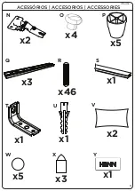
Page 23: ...ACESS RIOS ACCESORIOS ACCESSORIES ITM I718 x2 x2 x4 x3 x5 x3 x1 x1 x1 x46 x1 N Q T V W X Y U R S O P x5 3...

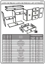
Page 24: ...1 LATERAL DIREITA 772 410 12 6 1 1 01 BASE 980 410 12 7 1 1 01 TAMPO 980 410 12 8 1 1 02 MOLDURA LATERAL 390 50 15 9 1 1 01 MOLDURA SUPERIOR 917 48 15 10 1 1 01 FUNDO MAIOR 795 394 3 11 1 1 02 FUNDO C...

Page 25: ...Fix the slides in these holes Para a desmontagem da corredi a siga a instru o ao lado Para el desmontaje de la diapositiva siga las instrucci n en el lado For disassembly of the slide follow the inst...

Page 26: ...de estos agujeros Fix the slides in these holes Para a desmontagem da corredi a siga a instru o ao lado Para el desmontaje de la diapositiva siga las instrucci n en el lado For disassembly of the slid...

Page 27: ...AS NECESS RIAS ACESS RIOS REQUERIDOS PASSO 3 PE AS REQUERIDAS 3 TAMPO DAS GAVETAS x1 1 DIVIS O x1 2 PRATELEIRA FIXA x1 C 03 PASSO 4 4 LATERAL ESQUERDA x1 5 LATERAL DIREITA x1 C 03 PE AS REQUERIDAS FER...

Page 28: ...ITM I718 C C C C C C 6 P P P P P P B B B B B B 6 8 PASSO 5 PE AS REQUERIDAS FERRAMENTAS NECESS RIAS ACESS RIOS REQUERIDOS 6 BASE x1 B 05 C 06 P 05...

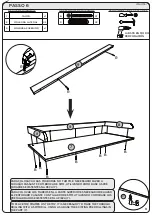
Page 29: ...OR ES NECESARIO REALIZAR EL PERFORADO PASANTE CON TALADRO DE 5MM UTILIZANDO COMO BASE LOS PRETALADRADOS EXISTENTES EN LA PIEZA 7 TO PLACE THE FRAMES ON THE TOP IT IS NECESSARY TO MAKE THE THROUGH DRIL...

Page 30: ...ximo das bordas da frente das Laterais 04 e 05 2 Angles near the front edges of the Sides 04 and 05 2 ngulos cerca de los bordes frontales de los lados 04 y 05 7 4 5 10 PASSO 7 FERRAMENTAS NECESS RIAS...

Page 31: ...ITM I718 12 11 11 10 I I I I I I J S 11 PASSO 8 10 FUNDO MAIOR x1 11 FUNDO CRU x2 12 FUNDO MENOR x1 I 39 J 10 S 01 PE AS REQUERIDAS FERRAMENTAS NECESS RIAS ACESS RIOS REQUERIDOS...

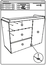
Page 32: ...ITM I718 PASSO 9 13 PORTA x1 D 01 E 04 N 02 O 01 PE AS REQUERIDAS FERRAMENTAS NECESS RIAS ACESS RIOS REQUERIDOS M N O N N D N E E 13 13 13 13 4 12 ITM I718...

Page 33: ...SS RIAS ACESS RIOS REQUERIDOS PASSO 11 15 LADO DE GAVETA x6 16 FUNDO DE GAVETA x3 17 RIPA DE TR S x3 H 06 V PE AS REQUERIDAS FERRAMENTAS NECESS RIAS ACESS RIOS REQUERIDOS 1 2 3x 3x F R V K 15 Cantonei...

Page 34: ...ITM I718 F Q Q G L F F F F F F K F 14 3x 3x 3x 4 3 5 14 F 24 G 06 L 06 Q 03 V PASSO 12 14 FRENTE DE GAVETA x3 PE AS REQUERIDAS FERRAMENTAS NECESS RIAS ACESS RIOS REQUERIDOS ITM I718 V V 14 15 14 14...

Page 35: ...ed load 980mm 895mm 430mm Imprescind vel a fixa o do produto na parede a n o coloca o destas ferragens para fixa o A E T e U poder permitir que o produto vire causando acidente Es imprescindible la fi...

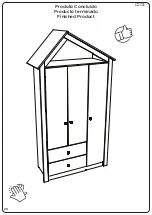
Page 36: ...ITM I718 16 REV 001 Produto Conclu do Producto terminado Finished Product...

Page 37: ...clus o da montagem El sistema de montaje de los productos funciona de acuerdo con el orden creciente de los n meros indicados en el dibujo Ej 01 02 03 04 hasta la conclusi n del montaje AVISO ADVERTEN...

Page 38: ...s II S utilize o ber o quando estiver totalmente montado conforme as orienta es do Manual de Instru es e ap s certificar que seus sistemas de travamento est o devidamente acionados III O Ber o deve se...

Page 39: ...est totalmente montado de acuerdo con las instrucciones del Manual de instrucciones y despu s de asegurarse de que sus sistemas de bloqueo est n debida mente accionados III La cuna debe colocarse sob...

Page 40: ...in accordance with the instructions in the Instruction Manual and after making sure that your locking systems are properly engaged III The crib must be placed on a horizontal floor IV For cribs with a...

Page 41: ...A O DA CONFORMIDADE REFEREM SE SOMENTE AO BER O THE INMETRO REGISTRATION AND THE CONFORMITY IDEN TIFICATION SEAL REFER ONLY TO THE CRIB EL REGISTRO EN EL INMETRO Y EL SELLO DE IDENTIFICACI N DE LA CON...

Page 42: ...menor que 20mm e maior que 23mm Para no comprometer la estructura de la cuna el espacio entre las piezas 03 y 05 no puede ser menor que 20mm y mayor que 23mm In order not to compromise the structure o...

Page 43: ...part 06 Fijar tornillo A antes de fijar la pieza n 06 Fura o para Ber o Op o mais baixa do lastro Perforaci n de cuna Opci n de lastre inferior Cradle Drilling Lower Ballast Option Fura o para Ber o O...

Page 44: ...ntre os lastros da extremidade com as laterais dever ser de 11mm For the higher option the distance between the end base frame to the sides should be 11mm Para la opci n m s alta la distancia entre lo...

Page 45: ...he torque at 15 to attach the rail and base frame Para n o comprometer a estrutura do ber o o espa o entre as pe as 03 e 10 n o pode ser menor que 20mm e maior que 23mm Para no comprometer la estructu...

Page 46: ...de fun o Para la Cuna Mini Cama Bala de Menta los lostros de la base no pueden ser removidos del travesa estructural para fines de transporte almacenamiento y o alteraci n de funci n For the Mini Min...

Page 47: ...ser utilizadas para a montagem do ber o cama To assemble the crib bed remove the parts maked with x and the reaining parts should be used for assembly it Para el montaje de la cuna cama sacar las piez...

Page 48: ...el montaje de la cuna cama la pieza 03 debe ser desplazada en la parte externa del lastre como se muestra arriba To install the crib bed the piece 03 must be moved for the outside of the base frame as...

Page 49: ...as para a montagem da mini cama To assemble the mini bed remove the parts marked with X and the remaining parts should be used to assemble the mini bed Para el montaje de la mini cama sacar las piezas...

Page 50: ...e a de n 02 para a montagem da peseira e a pe a de n 06 para a montagem da cabeceira Para el montaje de la Mini Cama es necesario utilizar la pieza de n 02 para el montaje de la peseera y la pieza de...

Page 51: ...eral inferior 01 na travessa estrutural 03 deve ser feita as fura es For fixing the lower side 01 on the structural cross member 03 drills must be made Para la fijaci n del lateral inferior 01 en el t...

Page 52: ...x6 09 1 1 02 Lastro maior 6mm Lastre mayor 6mm 6mm Largest Base Frame 595x420x6 10 05 1 1 01 Grade fixa Rejilla fija Fixed Rail 1300x670x25 11 1 1 01 Suporte mosquiteiro 1320mm Soporte de mosquiteros...

Reviews: