background image

8 • 

Important: Always read and follow instructions.

Result of the Measurement and Weight 

Application

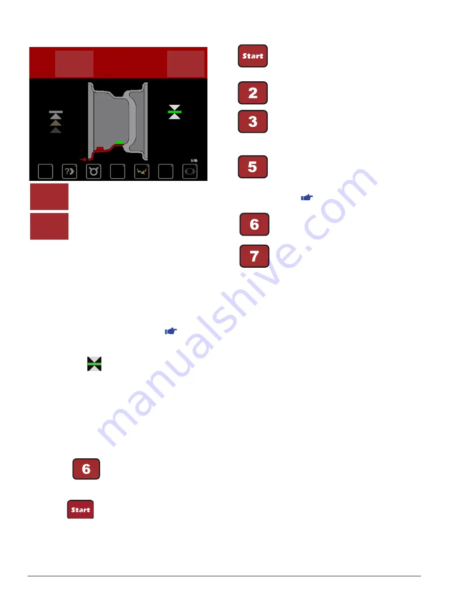
Inside unbalance indicator

Outside unbalance indicator

If the unbalance is out of tolerance:

1.

 At the end of the spin, the wheel automatically 

comes near to the outer side (on the inner side if the 

outer side is already within tolerance). In case of both 

sides (or static) within tolerance, no approaching is 

carried out. The spindle is automatically locked in cor-

rection position (if not disabled the spindle lock and for 

rotation speeds less than 20 rpm).

If the acoustic signal is enabled ( (

selects the correction type

displays the residual out-of-balance

(option) 

wheel locks/unlocks

main functions screen

(


MENU ACCESS DIAGRAM) 


 MENU - 

ACOUSTIC SIGNAL), a beep will sound when the 

correction position has been reached.

2.

 The symbol 

14

ENGLISH

Use and maintenance manual

Use of the wheel balancer

If the unbalance is out of tolerance:

1. At the end of the spin, the wheel automatically comes near to the outer side (on the inner side if the

outer side is already within tolerance). In case of both sides (or static) within tolerance, no
approaching is carried out.

 The spindle is automatically locked in correction position (if not disabled

the spindle lock and for rotation speeds less than 20 rpm).
If the acoustic signal is enabled (


MENU - ACOUSTIC SIGNAL

), a beep will sound when the correction

position has been reached.

2. The symbol 

 is shown on the display on the side corresponding to the active correction plane.

If a flashing arrow appears, move slightly by hand the wheel to complete positioning on the correction plane.

3. Manually apply the number of weights shown on the display on the rim at 12 o’clock using clip-on weights:

Inside unbalance indicator

Outside unbalance indicator


.

4. Press

 to position the wheel in proximity of the other side and correct the unbalance according to 

what is shown on the screen

5. After applying the weights, spin the wheel to check the correction made checking that both planes are within

tolerance.

Enabled buttons:

measuring spin with closed guard/automatic wheel positioning in proximity of the correction position  
with open guard

 is shown on the display on the 

side corresponding to the active correction plane.

If a flashing arrow appears, move slightly by hand 

the wheel to complete positioning on the correction 

plane.

Note:

 If the out-of-balance is less than the chosen 

threshold value, “0” appears instead of the out-of-

balance value to indicate, on that particular side, that 

the wheel is in tolerance; If AUTOADAPTIVE is dis-

abled, press 

ENGLISH

...

Indicators, selection made

Push button, FUNCTIONS MENU

Push button, menu selection confirmation

Push button, cycle start

Push button, cycle stop

 to display the FINE MODE value 

below the chosen threshold.

3.

 Press 

ENGLISH

...

Indicators, selection made

Push button, FUNCTIONS MENU

Push button, menu selection confirmation

Push button, cycle start

Push button, cycle stop

 to position the wheel in proximity 

of the other side and correct the unbalance according 

to what is shown on the screen

4.

 After applying the weights, perform spin check to 

check the correction made checking that both planes 

are within tolerance.

Enabled buttons:

measuring spin with closed guard/auto-

matic wheel positioning in proximity of 

the correction position with open guard

enables the indication of the longitudinal 

position of the out-of-balance

enables the unbalance SPLIT function

selects the correction mode. When the 

mode is changed, the unbalance values 

are recalculated automatically on the basis 

of the previous spin. Simultaneous display 

of the static unbalance can be 

enabled through the special function in 

Setup ( (

selects the correction type

displays the residual out-of-balance

(option) 

wheel locks/unlocks

main functions screen

(


MENU ACCESS DIAGRAM) 


  STATIC ALWAYS ENABLED)

displays the residual out-of-balance 

(option)

wheel locks/unlocks.

FI

FE

.25

1.75

1.00

2.00

1.25

1.50

3
4
5

FI

FE

FI

FE

.25

1.75

1.00

2.00

1.25

1.50

3
4
5

FI

FE

FI

FE

.25

1.75

1.00

2.00

1.25

1.50

3
4
5

FI

FE

FI

FE

.25

1.75

1.00

2.00

1.25

1.50

3
4
5

FI

FE

FI

FE

.25

1.75

1.00

2.00

1.25

1.50

3
4
5

FI

FE

Summary of Contents for Coats 1185

Page 1: ...ors Safety Instructions Set Up Instructions Operation Instructions Maintenance Instructions See Balancing Your First Tire on page 1 1185 Wheel Balancer 1601 J P Hennessy Drive La Vergne TN USA 37086 6...

Page 2: ...ii Important Always read and follow instructions Readentiremanualbeforeassembling installing operating or servicing this equipment NOTICE...

Page 3: ...Application 8 Balancing with a Mix of Adhesive and Clip On Weights and Static Balancing 9 Static Unbalance 10 Exact Positioning of the Adhesive Weight by Means of the Gauge with Clips 10 Hide the Adhe...

Page 4: ...n hair is recommended Do not wear jewelry loose clothing neckties or gloves when operating the balancer 11 Keep work area clean and well lighted Cluttered and or dark areas invite accidents 12 Avoid d...

Page 5: ...the place of safe operating practices Always wear durable work clothing during tire service activity Loose fitting clothing should be avoided Tight fitting leather gloves are recommended to protect op...

Page 6: ...angers warnings and cautions in this manual For additional copies of either or further information contact Hennessy Industries LLC 1601 JP Hennessy Drive LaVergne TN 37086 615 641 7533 or 800 688 6359...

Page 7: ...pers to measure wheel width Use keypad to enter Width value 6 Lower the hood press Start wheel spins and unbalances are measured and displayed The corrective weight amount appears in the digital reado...

Page 8: ...erly installed operated and maintained A Video Display Panel B Touch Control Panel C Weight Tray with Pockets for Corrective Weights D Hood Guard E Offset Arm Measures A D of Tire Wheel shown in home...

Page 9: ...tant Always read and follow instructions 3 ENGLISH Indicators selection made Push button FUNCTIONS MENU Push button menu selection confirmation Push button cycle start Push button cycle stop Control P...

Page 10: ...ft faceplate and that the hub nut engages the threaded shaft for at least four complete turns To assist in centering the wheel properly rotate the wheel and the shaft while tightening the hub nut Stan...

Page 11: ...e an additional cone as a spacer between the mounting cone and the hub nut The wheel must be forced firmly against the faceplate Note Do not front cone chrome or clad wheels Front Cone Collet Mounting...

Page 12: ...button FUNCTIONS MENU Push button menu selection con Push button cycle start Push button cycle stop Manual width setting Press Indicators selection made Push button FUNCTIONS MENU Push button menu sel...

Page 13: ...U ACOUSTIC SIGNAL the dimensions acquisition is accompanied by a beep Set the gauge to the rest position Slowly lower the guard and perform a measurement spin Note If AutoAdaptive correction method is...

Page 14: ...ing to what is shown on the screen 5 After applying the weights spin the wheel to check the correction made checking that both planes are within tolerance Enabled buttons is shown on the display on th...

Page 15: ...ht at 12 o clock Adhesive weight at the point indicated by the internal laser After dimension acquisition in ALU mode pressing the buttons FI FE 25 1 75 1 00 2 00 1 25 1 50 3 4 5 FI FE FI FE 25 1 75 1...

Page 16: ...possible in the event of static unbal ance or ALU external side and is used to hide any adhesive weights correcting unbalance behind the rim spokes 1 Position the static unbalance or outside ALU in th...

Page 17: ...asurements and dimensions screens E 3 4 5 E 3 4 5 Automatic Minimization of Static Unbalance This program is designed to improve the quality of balancing without any mental effort or loss of time by t...

Page 18: ...reduced by compensating when possible tire and rim out of balance values It requires two runs rotating the tire on the rim on the second run Having performed a run press 75 2 00 1 50 3 4 5 FI FE 1 75...

Page 19: ...Important Always read and follow instructions 13 Menu Menu Access Diagram PASSWORD press in sequence the following buttons...

Page 20: ...and entering the password returns to the previous screen returns to the measurement screen Each horizontal line indicates the number of clip on and adhesive weights used to balance the wheels in the...

Page 21: ...ress Enabled buttons confirms cancels the diameter gauge calibration func tion if has erroneously been accessed Balancing machine calibration To calibrate the balancing machine use a a 2 ounce calibra...

Page 22: ...sition is indi cated in correspondence to the laser 6 o clock to facilitate rim cleaning and adhesive weight application Wheel locking enable OFF disabled both the wheel locking and the auto matic whe...

Page 23: ...for easier trouble shooting Consult the extraordinary maintenance manual or contact Technical Service Diagnostics Inconsistent Unbalance Readings In some cases when a wheel that has just been balance...

Page 24: ...eed too low during detection During the unbalance measurement revolutions the wheel speed has fallen to below 42 rpm Make sure that a vehicle wheel is mounted on the wheel balancer Use the self diagno...

Page 25: ...ns on the power board Replace the computer board Err 23 Wheel positioning in proximity of the correction position error Check in self diagnostics that the encoder functions properly Check that there a...

Page 26: ...ier promptly Support your claim with copies of the bill of lading freight bill invoice and photographs if possible Although COATS responsibility ceases upon delivery of the shipment to the carrier we...

Page 27: ...ncer Make sure the location selected has enough room above and behind the unit so the hood can be raised completely The location must also pro vide working room for mounting and removing wheels Make s...

Page 28: ...he pallet and place it in its operating location Hood Installation 5 Remove one screw holding the Hood bracket to the balancer arm Fig 2 6 Align the Hood bracket with the balancer arm and secure with...

Page 29: ...Important Always read and follow instructions 23 Notes...

Page 30: ...24 Important Always read and follow instructions Notes...

Page 31: ...Important Always read and follow instructions 25 Notes...

Page 32: ...85611754 00 08 20 Copyright 2020 Hennessy Industries LLC All Rights Reserved Printed in USA...

Reviews: