10 •
Important: Always read and follow the information box instructions.
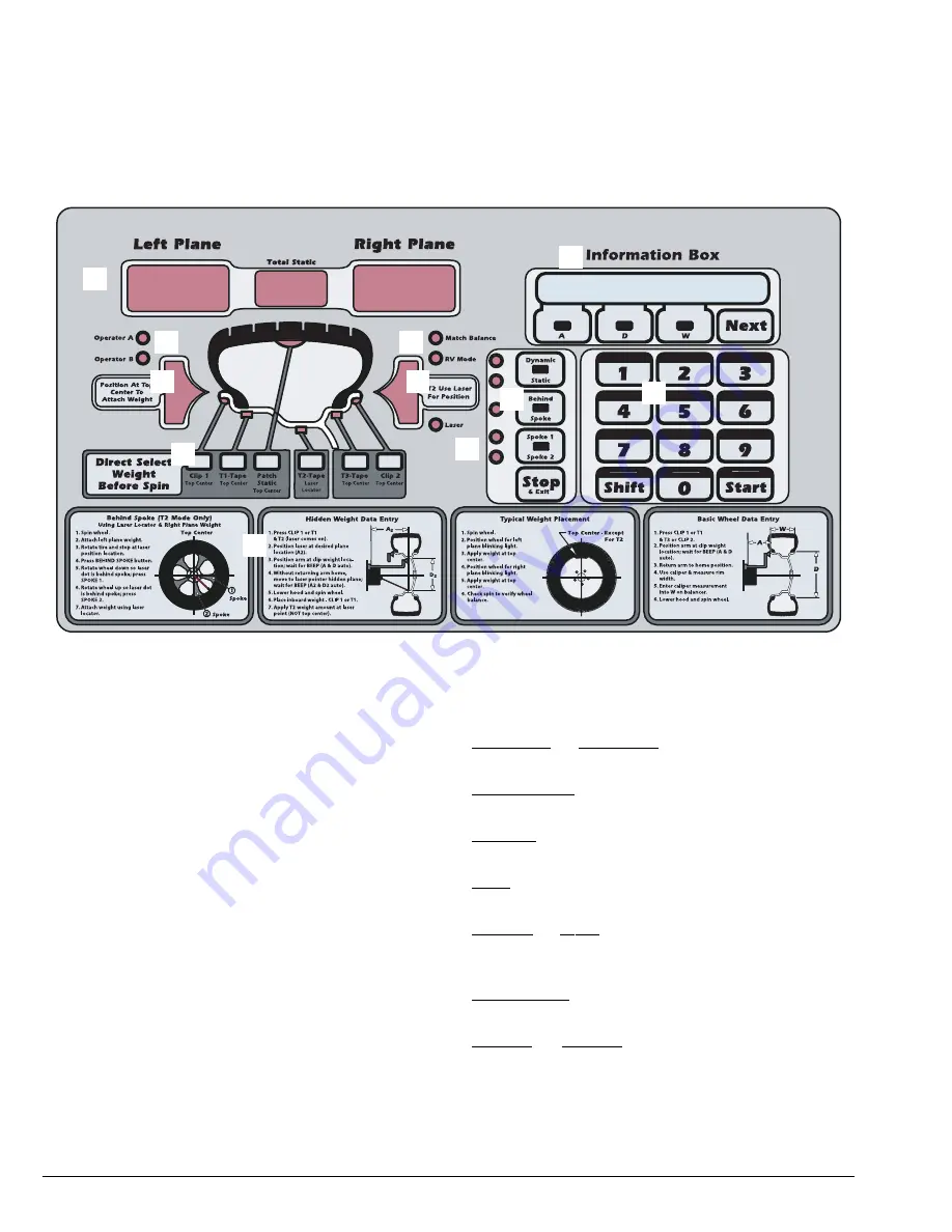
Weight Display and Weight Position LEDs
Two weight display windows (one inboard “Left
Plane” and one outboard “Right Plane”) are positioned
above the wheel cross section diagram. After a wheel
measurement cycle, the balancer calculates the cor-
rective weight amount and indicates it in the appropri-
ate display window. All weight readings are shown in
ounces or grams.
The “Total Static” window indicates the value of the
total static unbalance. See MATCH BALANCE
(Optimization) on page 16 for further details.
Located on either side of the wheel cross section dia-
gram are the weight position LED bars, one inboard
(Left Plane) and one outboard (Right Plane). After a
measurement cycle, rotate the wheel until the center
weight position LED bar is blinks, indicating the correct
weight placement position is at top-dead-center.
Note:
When in laser mode (T2-Tape Laser Locator),
special blinking bars appear on either side of the cen-
ter bar to indicate the correct weight placement posi-
tion (right plane).
Mode LED Indicators
The mode’s LED will illuminate to indicate the mode
is activated. Modes are as follows:
Operator A or Operator B - when illuminated, indi-
cates which operator memory is selected.
Match Balance - when illuminated, indicates that the
Match Balance (Optimization) mode is activated.
RV Mode - when illuminated, indicates that the 0.50-
ounce RV (heavy wheels) mode is activated.
Laser - when illuminated, indicates that the Laser
Guided Operation™ system is activated.
Dynamic or Static - press to cycle through balance
modes. For additional information, see Balance
Options, page 11.
Behind Spoke - when illuminated, indicates that the
behind spoke mode is activated.
Spoke 1 or Spoke 2 - when illuminated, indicates
spoke location selection.
Weight Display Windows
Mode LED Indicators
Left Weight Position LED Bars
Right Weight Position LED Bars
Direct Select™ & Wheel Cross-section Diagram
Information Box
Balancer Options
Keypad Group
Instructional Pane
Figure 13 - Control Panel Feature Reference


