

COATS 4050A Tire Changer • 11
Maintenance Instructions
Read and follow all the maintenance instructions
provided in this manual to keep the machine in
good operating condition. Refer to the other
materials received with the unit and to the service
bulletins from the manufacturer for additional
instructions on proper maintenance and service.
Regular inspections and proper maintenance are
essential to preventing accidents and injuries.
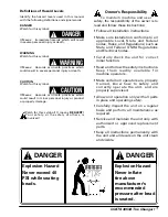
Before making any
i n s p e c t i o n ,
adjustment, or repair,
disconnect the power source and block out all
moving parts to prevent injury.
Keep the machine and
the immediate work
are clean. Do not use
compressed air to remove dirt and debris from the
machine. Foreign material may be propelled into
the air and into operator or bystander causing
personal injury.
Wear protective
clothing and use eye
protection when
making any adjustments or repairs to the
machine.
Cylinder Maintenance
The unique design of the hydraulically dampened
7” cylinder controls bead loosening, mounting,
and demounting. Internal sealing surfaces are
chrome plated to provide long seal life. A small
amount of oil is ususally lost after a period of time
in lubricating the seals. It is important that the
cylinder be filled to the proper level at all times. If
the oil becomes low, the machine will surge at the
beginning of its stroke. Cylinder oil level should be
checked before initial operation and weekly
thereafter. A special hydraulic oil must be used.
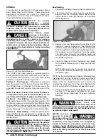
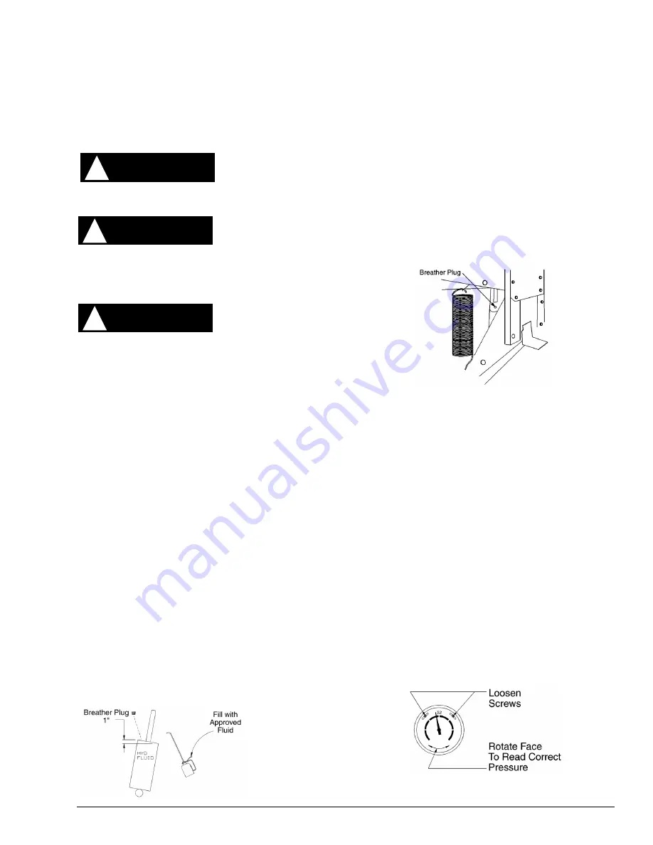
Filling 7” Cylinders
Fill only with COATS Hydraulic Oil (part #8101411)
or an approved alternate choice (Empak 4061, or
Shell Tellus 21). Do not use motor oil or brake
fluid.
1.
Remove the front panel by removing 4 self
tapping bolts and 3 self tapping screws.
2.
Depress and hold the foot pedal to extend the
cylinder to the top of its stroke.
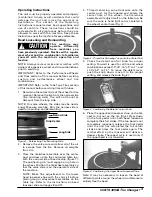
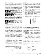
3.
Remove the plastic breather plug. Fill the
cylinder to within 1” to 1-3/16” of the access
hole in the top. Be careful no dirt falls in
through the hole (figure 26).
4. Reinstall breather plug and reattach front panel.
Figure 26 - Filling
the 7” Cylinder
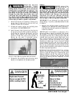
5” Cylinders
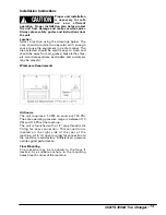
The 5” cylinder requires periodic lubrication. This
can be performed without removing the cylinder
from the unit.
1.
Remove the side panel on the foot pedal side
of the unit by removing 4 hex bolts and 3 hex
screws.
2.
Depress and hold the foot pedal to extend the
cylinder to the top of its stroke.
3.
Remove the white breather plug on the cylinder
and add 1/2 ounce of 10W-30 motor oil with a
funnel or long spout oil can (figure 27).
IMPORTANT: Do not fill the 5” cylinder with oil.
4.
Reinstall the breather plug and reattach the
side panel.
Figure 27 - Lubricating the 5” Cylinder
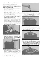
Pressure Gauge Maintenance and Calibration
Check the tire pressure gauge function on the unit
daily, and perform an accuracy check monthly. Use
a pressurized tire and a high quality stick pressure
gauge. If necessary, calibrate the dial of the
machine gauge.
1.
Pressurize a large 15” tire to 30PSI and
measure the pressure exactly with a high
quality extension type tire gauge. Connect the
air chuck to the tire.
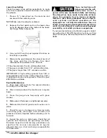
2.
Remove the gauge lens and loosen the 2
screws at the top of the gauge and rotate the
gauge face until the indicator is pointed at the
correct pressure as read with the extension
type tire gauge (figure 28).
3.
Tighten gauge face screws and replace lens.
If gauge is defective, replace it immediately (part
#8107980).
Check the function of the pressure limiter weekly
as part of your pressure gauge maintenance and
calibration.
igure 28 - Calibrating Pressure Gauge
WARNING
!
WARNING
!
CAUTION
!


