


Installation Instructions
Proper unit installation
is necessary for safe
use and efficient
operation. Proper installation also helps protect
the unit from damage and makes service easier.
Always place safety poster and instructions near
the unit.
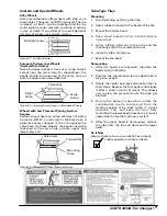
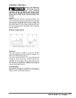
Location
Select a location using the drawings below. The
area should provide the operator with enough
space to use the equipment in a safe manner. The
area selected should be well lit, easy to clean and
should be away from oil, grease, brake lathe chips,
etc. Avoid areas where bystanders and customers
may be present.
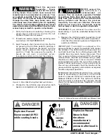
Workspace Requirements
Air Source
The unit requires a 5 CFM air source at 150 PSI.
The safe operating pressure range is between 110
PSI and 175 PSI at the machine.
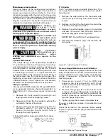
The unit is furnished with a 1/4" pipe thread male
fitting for easy connection. This connection is
located on the right side of the rear of the
machine. A 1/4" ID hose (or pipe) for connection to
the machine is satisfactory. Sufficient air pressure
assures good performance.
Floor Mounting
The machine may be mounted to the floor if
desired. Use suitable anchors in the mounting
holes at each corner of the machine.
COATS 4050A Tire Changer • 13
CAUTION
!


