
Inflation
Tire inflation is performed in three steps: Bead
Seal, Bead Seat and Inflation. These steps are
explained in detail on page 10. Read the
explanation of each step and understand them
thoroughly before proceeding.
Check for proper
inflation gauge
operation. Accurate
pressure readings are important to safe tire
inflation. Refer to the Operating Maintenance
section of this manual for instructions.
Tire failure under
pressure is hazardous.
This tire changer is not
intended to be a safety device to contain
exploding tires, tubes, wheels, or bead sealing
equipment. Inspect tire and wheel carefully for
match, wear, or defects before mounting. Always
use approved tire bead lubricant during mounting
and inflation.
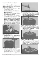
Figure 13 - Air-Flate Pedal Positions
The COATS Air-Flate system is operated with a
three position foot pedal (referred to as the Air-
Flate pedal). Each position of the Air-Flate pedal
performs a specific function (figure 13):
Position 1 - Tire Pressure –
When foot is removed
from the pedal, it will return to this position. When
the inflation hose is attached to the tire valve, the
pressure gauge will register the pressure in the
tire.
NOTE: The clip-on chuck on the end of the hose is
an important safety aid and should always be an
open style with all parts in proper working order.
Position 2 - Tire Inflation –
By pressing the Air-
Flate pedal down to this first activated position, full
air line air pressure is applied to the inflation hose
for tire inflation. Remove your foot from the pedal
(position 1) to read tire pressure on the pressure
gauge. See page 7 for pressure limiter information.
Position 3 - Bead Sealing –
Press the pedal down
fully and full air line air pressure is applied to the
inflation hose and to the bead seal jets mounted in
the top cover.
Use Position 3 for bead
sealing only. Do not use
this position without a
tire and wheel positioned on the tabletop. Dirt and
debris could be blown into the air with enough
force to injure the operator or bystanders. Do not
use the position to inflate a tire.
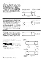
Bead Sealing
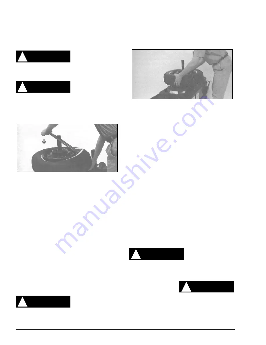
1.
Connect the inflation hose to the tire valve stem.
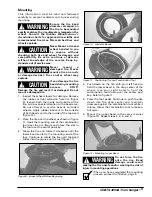
2.
Lift tire so that the upper bead is against the
edge of the rim to create a seal. Be sure the
upper bead is over the bottom of the valve
stem (figure 14).
Figure 14 - Bead Sealing
3.
Depress the Air-Flate pedal to position 2 and
hold for 1 second to begin air flow through the
inflation hose, then depress the Air-Flate pedal
fully to position 3, hold very briefly (less than 1
full second), and remove foot from the pedal.
The blast of air through the inflation hose and
the top cover jets will expand the tire and seal
the beads (figure 14).
4.
Check to make sure that the beads are sealed
to the wheel. Repeat step 3 if they are not fully
sealed.
NOTE: Allow time for the surge tank pressure
to recover before depressing the pedal to
position 3 again.
TIP: If the tire and wheel are properly lubricated and
the operator cannot achieve bead seal after 3
attempts, it may help to remove the valve core.
Remove the air chuck from the valve stem and
unscrew the valve core from the stem. Reattach the
air chuck and perform the bead seal operation again.
5.
Check tire pressure (Air-Flate pedal must be in
position 1). If pressure is indicated in tire, bead
seal has been obtained. Proceed to Bead
Seating.
Bead Seating
Operator should keep
hands, arms, and
entire body away from
the tire and wheel during the remaining Bead Seat
and Inflation procedures. Do not stand over tire,
as personal injury could result.
NEVER increase air
pressure to exceed 40
PSI when attempting
Bead Seat. If unable to obtain Bead Seat,
something is wrong. Deflate tire completely,
inspect both the tire and wheel, and correct any
problems found. Relubricate both tire beads, and
reattempt Bead Seal and Bead Seat procedures.
Follow all safety instructions in this manual and
on machine.
6 • COATS 4050A Tire Changer
CAUTION
!
DANGER
!
CAUTION
!
WARNING
!
WARNING
!