background image

Important: Always read and follow the operating instructions.

• 9

Installation Instructions

Proper unit installation is necessary for safe
use and efficient operation. Proper installa-
tion also helps protect the unit from dam-
age and makes service easier. Always place
safety poster and instructions near the unit.

Location

Select a location that provides the operator with

enough space to use the equipment in a safe manner.
The area selected should be well lit, easy to clean and
should be away from oil, grease, brake lathe chips, etc.
Avoid areas where bystanders and customers may be
present.

Floor Mounting

The machine should be securely bolted to the floor

with suitable anchors using the hole at each corner of
the machine base.

Assembly Instructions

Please inspect this unit for damage/missing parts

prior to use.

Carton Contents (boxes marked 1 through 3):

Contains the base, tower and table top for your RC-
50M Manual tire changer. Be sure to check all contents
prior to assembly.

(Optional) Carton Contents (box marked 4):

Contains the Bead Loosener. Be sure to check all con-
tents prior to assembly.

Base Assembly:

Enclosed with base unit you will

find 4 (four) anchor bolts (1/2” X 3”) choose the loca-
tion for the base at this time being sure to position the
RC-50M in a clear working area. (It is suggested that
the unit is firmly mounted to the floor prior to attaching
the tower or table top.) Attach the tool tray to the base
with supplied hardware.

Tower Assembly:

Using the supplied hardware 4

(four) (12mm X 55mm hex bolts) that attaches the
tower to the base of the RC-50M, position the tower in
place. Attach the swing arm to the tower, (at this time
it is suggested that grease be added to the pivot shaft.)
The slider may be put into place at this time, (add the
return spring prior to placing the slider in the swing-
arm guide) once placed attach the bead head. Check
travel, clearances and locking mechanism prior to use. 

Table Top  Installation:

Prior to installation BE SURE

TO  PLACE THE TABLE TOP WITH THE  LOCKING  KNOB
FACING FORWARD FOR ACCESS WHEN RC-50M IS
IN USE. Once the table top has been positioned check
all clearances for complete 360-degree rotation. Place
wheel jaws at desired position, making sure to place

holding pin completely through the guild hole prior to
locking the wheel in place.

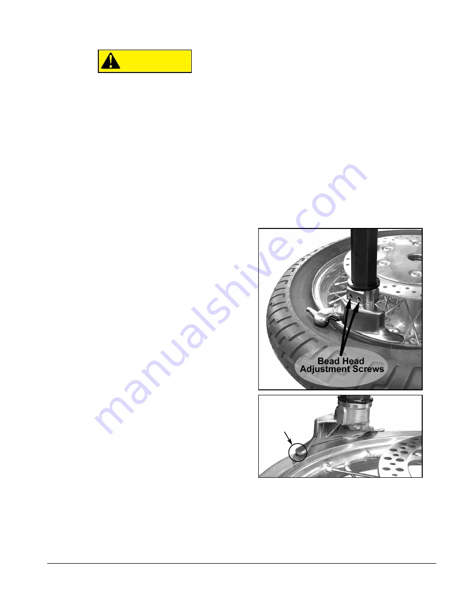
Bead-head Adjustment:

Prior to using your RC-50M

you should take a few moments to check the align-
ment of the bead-head. This is a simple procedure that
will require a 4.5mm hex wrench and an 18-inch wheel.
Set the jaws in place to accept the 18-inch wheel
(using a bare wheel will ease the adjustment process),
tighten the jaws so that the wheel is held in place.
Lower the bead head until contact is made between
the plastic rim protector and top outer edge of the
wheel. If they do not match-up, make the following
adjustment using the two adjusting screws (located
side-by-side on the bead-head mounting base, fig.1) If
needed, rotate the head until contact is made with the
wheel. The plastic protector should be touching the
wheel as close to the center as possible. The rear por-
tion of the bead head should overlap the outer edge of
the wheel so that there is approximately 1-3mm over-
hang (fig. 2.) Offset changes are made with the two
adjusting screws.

Assembly for (Optional) Bead Loosener:

Check all

contains prior to assembly. Attach support to the base
using the supplied hardware. At this point you may
now attach the link, breaker and lever arm to the sup-
port. The Bead Loosener will attach to the RC-50M by 
hooking on to the locating mount.

CAUTION

Fig 1.

Fig 2.

1-3mm

overhang

Summary of Contents for Coats Rim Clamp RC-50M

Page 1: ...READ these instructions before placing unit in service KEEP these and other materials delivered with the unit in a binder near the machine for ease of reference by supervisors and operators RC 50M Rim Clamp Tire Changer For servicing motorcycle andATV tire wheel assemblies See Operating Instructions on page 2 Installation Instructions Operating Instructions Safety Instructions Maintenance Instruct...

Page 2: ...s Rules and Regulations such as State and Federal OSHA Regulations and Electrical Codes Carefully check the unit for correct initial function Read and follow the safety instructions Keep them readily available for machine operators Make certain all operators are properly trained know how to safely and correctly operate the unit and are properly supervised Allow unit operation only with all parts i...

Page 3: ...manual with the following definitions and signal words DANGER Watch for this symbol It Means Immediate hazards which will result in severe personal injury or death WARNING Watch for this symbol It Means Hazards or unsafe practices which could result in severe personal injury or death CAUTION Watch for this symbol It Means Hazards or unsafe practices which may result in minor personal injury or pro...

Page 4: ...e Use for extra leverage when rotat ing table top during tire removal TableTop Rotating platform for tire changing Three Position Motorcycle Clamps Holds wheel to table top for tire changing 4 clamps 90 degrees apart Motorcycle DuckHead Mounts and demounts tire from wheel Bead Loosener Optional Use to loosen bead of tires Mounting Tabs Use to adjust bead loosener position to match tire rim combina...

Page 5: ...Important Always read and follow the operating instructions 1 Bead Loosener Optional Bead Loosener shown separately for clarity Part Number 85000503 ...

Page 6: ...ire at some time Figure 1 Remove Valve Core to Deflate Tire Loosening the beads on a partially or fully inflated tire is unsafe and causes excess movement and friction against the bumper pads and excessive wear on pivots Deflate the tire completely to prolong the life of your machine ATV Note It may be necessary on ATV wheels to leave 3 6 PSI in some of these wheels to facilitate bead loosening Ev...

Page 7: ...e the clamping screw clockwise to move the clamps inward or crank coun terclockwise to move the clamps outward Clamp motorcycle and ATV wheels from the outside clamps push inward against the outside rim edge Place rim flange into rear clamp and slowly move the other clamps inward until they contact the rim Observe closely to prevent tire wheel damage If clamps are properly positioned and the tire ...

Page 8: ...e the head to help with tool insertion Figure 10 Insert Bead Lifting Tool 12 Rotate the bead lifting tool down towards the wheel to lift the tire bead up and over the knob portion of the demount head The lift tool may be removed if desired figure 11 Figure 11 Lift Bead Over Demount Head 13 Rotate the wheel clockwise If additional lever age is needed insert the table top rotating handle into the re...

Page 9: ...eting the demount process proceed to MOUNTING CAUTION Important Always read and follow the operating instructions 5 Motorcycle ATV Operator Protective Equipment Always wear durable work clothing during tire serv ice activity Shop aprons or shop coats may also be worn however loose fitting clothing should be avoided Tight fitting leather gloves are recom mended to protect the operator s hands when ...

Page 10: ...ved lubricant figure 15 Figure 15 Lubricate Beads 4 Place tire over wheel and move swing arm into position Position the tire so that the lower bead is above the rear extension of the mount demount head and below the front knob figure 16 Figure 16 Position Tire Against Mount Demount Head 5 Turn the table top and rotate the wheel to mount the lower bead Use the drop center of the wheel to reduce the...

Page 11: ... tire while wheel is clamped to the table top Remove tire and wheel assembly from machine to inflate Use a remote controlled inflation device when inflating to seat beads use a small amount of air inter mittently never exceed the tire manufacturer s recom mendation when inflating If beads do not seat remove air and relubricate beads After tire is properly inflated secure bead locks were required A...

Page 12: ...amps should be inspected and metal chips and dirt removed from the serrations with a wire brush once a month G Make sure all fasteners are securely tightened H Make certain that all guards and covers are in place I Check for worn damaged or missing parts including grips and protective covers Replace them before allowing the unit to be used J On a daily basis inspect the unit and check to be certai...

Page 13: ...the pivot shaft The slider may be put into place at this time add the return spring prior to placing the slider in the swing arm guide once placed attach the bead head Check travel clearances and locking mechanism prior to use Table Top Installation Prior to installation BE SURE TO PLACETHETABLETOP WITHTHE LOCKING KNOB FACING FORWARD FOR ACCESS WHEN RC 50M IS IN USE Once the table top has been pos...

Page 14: ...NG 85000719 RIM PROTECTOR 85000720 RUBBER GRIP 85000721 FLASH BOLT PART NO DESCRIPTION 85000722 NYLON NUT 85000723 PIN 85000724 ADJUSTER HEAD 85000725 HANDLE 8184712 PLASTIC BOOTIE 10 Important Always read and follow the operating instructions Parts List ...

Page 15: ...Important Always read and follow the operating instructions 11 Notes ...

Page 16: ... tire on a rim inspect the rim for rust tough spots bent edges or cracks that could prevent the tire from seat ing right If you spot any of these problems don t mount the tire until the rim has been checked by your shop foreman Inspect the tire for bead damage MOUNT Once you ve made sure the tire is OK and the right size and the rim is OK mount the tire safely NEVER ever lean over the tire when yo...

Reviews: