background image

Model HCH-930/932

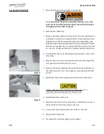
2-8.  FLOAT SWITCH

1. Disconnect the electrical supply to the cabinet.

To avoid electrical shock or property damage, move the
power switch to OFF and disconnect main circuit breaker,
or unplug cord at wall receptacle.

2. Remove the cabinet top.

3. Remove the float switch wire from the L1 wire nut, and check for

continuity across this wire and terminal 3 of the solid state relay.
With the float in the raised position, the circuit should be open.
With the float in the lowered position, the circuit should be closed.
If the float is not defective, reconnect the float switch wire to the
L1 wire nut.  If it proves defective, continue with the steps below.

4. Cut the float switch wire that attaches to terminal 3 on the solid

state relay.

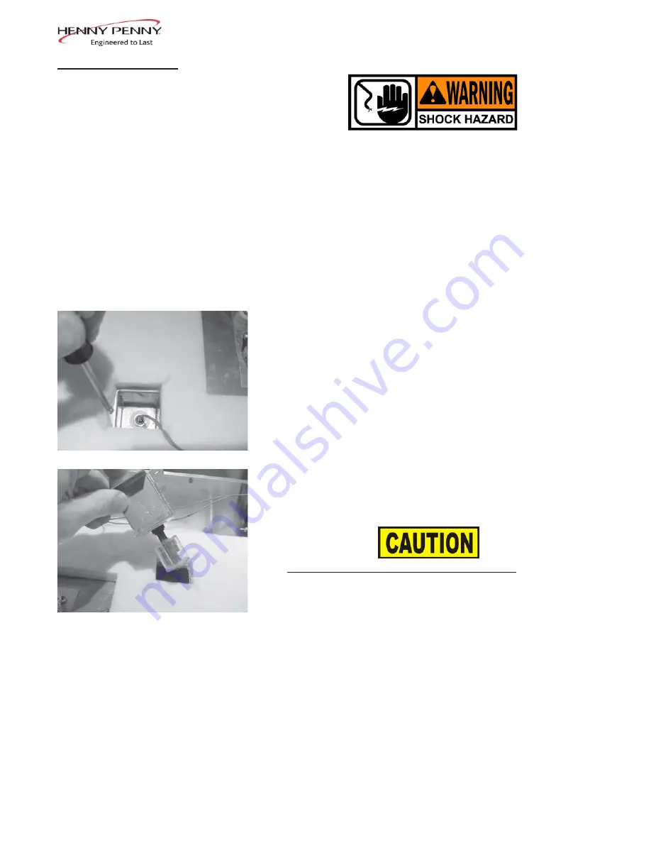
5. Remove the 2 screws securing the float switch well and pull the

well up and out of the heater box cover.

6. Remove the nut securing the float switch in the well and remove

the old float switch.  Save the 2 spacers removed with the float

                                                 Step 5

switch.

7. Install new float switch using the 2 white spacers from step 6.

Tighten the float switch nut finger tight only!  Over-
tightening the nut damages the float switch.

8. Reinstall the float switch well.

                                                 Step 6

9. Strip the end of the cut wire from step 4, and attach it to one of

the new float switch wires, using a wire nut.

10. Connect the other float switch wire to the L1 wire nut.

11. Replace the cabinet top.

12. Reconnect the electrical supply to the cabinet.

203

                              2-5

Summary of Contents for HCH-930

Page 1: ...TECHNICAL MANUAL Henny Penny Heated Holding Cabinet Model HCH 930 Model HCH 932...

Page 2: ......

Page 3: ...Clean Water Strainer 2 2 2 5 Replace Water Strainer 2 2 2 6 Cleaning Water Valve 2 3 2 7 Replacing Water Valve 2 4 2 8 Float Switch 2 5 2 9 Solid State Delay Timer 2 6 2 10 Blower 2 6 2 11 Heater 2 7...

Page 4: ...ii 703...

Page 5: ...especiallyimportantinformation CAUTION used without the safety alert symbol indicates a potentially hazardous situation which if not avoided may result in property damage CAUTION indicates a potential...

Page 6: ...bad B Cabinetsteaming Toomuchhumidityinside Remove one or more baffles or product soggy cabinet from water pan WATER SYSTEM A Waterpannotfilling Water supply off or Check water supply line disconnect...

Page 7: ...meter C Unit overheats Faulty thermostat Check thermostat Faulty blower Check blower and replace if bad POWER SECTION A With power switch Unit not connected to electrical Connect unit to electrical su...

Page 8: ...Model HCH 930 932 THIS PAGE INTENTIONALLY LEFT BLANK 1 4 703...

Page 9: ...llreadinfinity 2 3 DELIMINGWATER PAN Inspect the water pan and baffles every 10 days for lime buildup AND BAFFLES and clean when necessary Failure to keep the water pan and baffles free of lime buildu...

Page 10: ...Make sure water pan issecureagainsttheceilingofthecabinet 7 Replace the top drawer 8 Reconnectelectricalsupplytocabinet 2 4 CLEAN WATER STRAINER 1 Shutoffwatersupply 2 Remove the hex cap at the botto...

Page 11: ...the inlet side of the valve with a wrench and thenturnvalvecounterclockwiseuntilthevalveisfreefromthe fitting 9 Remove the 2 screws H from the coil retainer F 10 Remove the retainer and pull the coil...

Page 12: ...onnect the electrical supply to the cabinet 2 7 REPLACINGWATER VALVE 1 Follow steps 1 through 8 of section 2 6 To avoid electrical shock or property damage move the power switch to OFFand disconnect m...

Page 13: ...continuewiththestepsbelow 4 Cut the float switch wire that attaches to terminal 3 on the solid state relay 5 Removethe2screwssecuringthefloatswitchwellandpullthe well up and out of the heater box cove...

Page 14: ...the back of the control panel with the 2 nutsremovedearlier 6 Replace the cabinet top 7 Reconnecttheelectricalsupply 2 10 BLOWER 1 Disconnecttheelectricalsupplytothecabinet To avoid electrical shock o...

Page 15: ...upply to the cabinet 2 12 HIGH LIMIT 1 Disconnect the electrical supply to the cabinet To avoid electrical shock or property damage move the power switch to OFF and disconnect main circuit breaker or...

Page 16: ...he2nutssecuringthebulbretainingclipsandremove thethermometerbulbfromtheclips 6 Removethenutsecuringthethermometertothemountingbrack et on the back of the thermometer body 7 Removethethermometerthrough...

Page 17: ...he cabinet 5 Pull the blower box up to expose the thermometer and thermo stat bulbs Carefully lay the blower and blower box off to one side 6 Removethe2nutssecuringthebulbretainingclipsandremove theth...

Page 18: ...rol panel 5 Remove the switch from the unit 6 Install the switch in reverse order Step 4 7 Replace cabinet top 8 Reconnect electrical supply to the cabinet 2 16 INDICATINGLIGHTS 1 Disconnect the elect...

Page 19: ...fan Step 3 4 Remove the 4 nuts and screws securing the fan and remove fan fromthecabinet 5 Install new fan in reverse order 6 Strip ends of cut wires and connect them to the new fan wires Step 4 7 Re...

Page 20: ...er the 2 drawer handle spacers over the screw holes so the handle screws pass through the spacers 2 19 DRAWER AND LINER Apply Loctite to screw threads when replacing drawer bearing kit BEARING REPLACE...

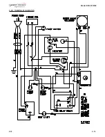
Page 21: ...Model HCH 930 932 807 2 13 2 20 WIRING DIAGRAMS...

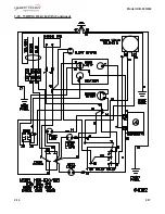
Page 22: ...Model HCH 930 932 2 14 807 2 20 WIRING DIAGRAMS Continued...

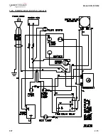
Page 23: ...Model HCH 930 932 807 2 15 2 20 WIRING DIAGRAMS Continued...

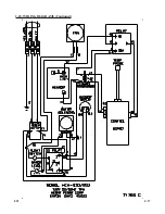
Page 24: ...2 20 WIRING DIAGRAMS Continued 2 16 807...
Page 25: ...2 20 WIRING DIAGRAMS Continued 807 2 17...
Reviews: