background image

        Model 290

Title

Fig. No.

Page No.

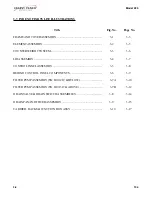
FRAME AND COVER ASSEMBLY .............................................................

3-1

3-3

ELEMENT ASSEMBLY ................................................................................

3-2

3-5

COUNTERWEIGHT SYSTEM .....................................................................

3-3

3-6

LID ASSEMBLY ...........................................................................................

3-4

3-7

CONTROL PANEL ASSEMBLY ..................................................................

3-5

3-8

BEHIND CONTROL PANEL COMPONENTS ...........................................

3-6

3-9

FILTER PUMP ASSEMBLY (SN: LG012JC & BELOW) .............................

3-7A

3-10

FILTER PUMP ASSEMBLY (SN: LG013JC & ABOVE) ..............................

3-7B

3-12

DRAIN VALVE & DRAIN SWITCH ASSEMBLIES ...................................

3-8

3-14

DRAIN PAN AND FILTER ASSEMBLY ......................................................

3-9

3-15

CARRIER, RACKS & JUNCTION BOX ASSY ..........................................

3-10

3-17

3-7.  INDEX OF PARTS LIST ILLUSTRATIONS

3-2

      104

Summary of Contents for OFE-290

Page 1: ...Henny Penny Open Fryer Electric Model OFE 290 TECHNICAL MANUAL ...

Page 2: ......

Page 3: ... 6 Power Pump Switch 2 5 2 7 Temperature Probe Replacement 2 6 2 8 Complete Control Panel Henny Penny 2 7 2 9 Contactors 2 8 2 10 Heating Elements 2 10 2 11 Drain Microswitch 2 13 2 12 Drain Valve and Extension 2 14 2 13 Nylatron Strips Replacement 2 15 2 14 Lid Couterweight CablesWiring Diagrams 2 17 Section 3 PARTS INFORMATION 3 1 3 1 Introduction 3 1 3 2 Genuine Parts 3 1 3 3 How To Order 3 1 3...

Page 4: ...Their usage is described below SAFETYALERTSYMBOLis used with DANGER WARNING or CAUTION which indicates a personal injury type hazard NOTICEisusedtohighlightespeciallyimportantinformation CAUTION used without the safety alert symbol indicates a potentially hazardous situation which if not avoided may result in property damage CAUTION indicates a potentially hazardous situation which if not avoided ...

Page 5: ...oubleshootingtable 3 Review all possible causes Then one at a time work throughthelistofcorrectionsuntiltheproblemissolved 4 Refer to the maintenance procedures in the Maintenance Section to safely and properly make the checkout and re pair needed If maintenance procedures are not followed correctly injuries and or property damage could result 1103 1 2 ...

Page 6: ...rature too low Check temperature setting Remove and replace tempera ture probe Fryer incorrect preheat Allow proper preheat time Slow fryer heat up recovery Faulty element Wrong cook button Be sure to select the correct pushed amount of product to be cooked C Product Shortening old Replace shortening greasy Temperature too low Check temperature setting Temperature not recovered when product was dr...

Page 7: ...cooking time Reduce cooking temperature Wrong cook button pushed Be sure to select the correct amount of product to be cooked Product flavor taste A Salty taste Breading mixture is too salty Sift breading after each use Incorrect breading mixture Discard old breading Incorrect choice of Use breading designed for breading the desired product B Burned taste Burned shortening favor Replace shortening...

Page 8: ...Overcooking Check cooking time Product not fresh Use fresh product B Bone color Using frozen product Use fresh product not proper black bone Improper processing of Use proper processing product black bone procedure for product Product not thoroughly Check cooking time cooked red bone Check cooking temperature C Breading falls Incorrect breading Use correct breading off procedures procedure Product...

Page 9: ... PC board Replace glass fuse in board Faulty POWER PUMP switch Check POWER PUMP switch per maintenance section on the POWER PUMP switch Faulty cord and plug Check cord and plug Check power at receptacle Faulty drain switch Check drain switch per maintenance section on drain switches Faulty PC Board Remove and replace control panel Faulty high limit control switch Check high limit control switch pe...

Page 10: ...sSection Points in contactor bad Check contactor per Heating Contactors Section Wire s loose Tighten Burnt or charred wire Replace wire and clean connection connectors Shortening Programmingwrong Check temperature setting overheating intheprogrammode Faulty PC board Remove and replace control panel Faulty temperature probe Remove and replace temperature probe Check contactor for not Check faulty c...

Page 11: ...ning Improperfiltering Refer to the procedure coveringfilteringtheshortening Coldzonefullofcracklings Filtershortening Improperrinsingafter Cleanandneutralizethe cleaningthefryer frypot rinsewithvinegar toremovethealkaline then rinse with hot water and dry frypot Shorteningwill Drainvalvecloggedwith Open valve push cleaning notdrainfromfrypot crumbs rodthroughdrainopeningfrom insideoffrypot Shorte...

Page 12: ...ition then back to ON if display shows E05 the heating circuits and temperature probe should be checked once the unit cools down the controlsshouldreturntonormal if E05 persists replace the controls E06 Temperature probe failure Turn switch to OFF position then back to ON if the display shows E06 the tempera ture probe should be checked once the temperature probe is repaired or replaced the contro...

Page 13: ...AY CAUSE PANEL BOARD CORRECTION E10 Highlimit Resetthehighlimitbymanuallypushingupontheredreset button ifthehighlimitdoesnotreset thehighlimitmustbe replaced per the High LimtTemperature Control Section E15 DrainSwitch Closethedrain usingthedrainvalvehandle ifdisplaystill shows E 15 check the drain microswitch per the Drain SwitchSection 1103 1 12 ...

Page 14: ...imeter shouldreadinfinity Do not move the fryer with hot shortening in the frypot or filter pan Severe burns can result from splashing hot shortening 4 Remove weights from the frame to easily access rear of fryer To ensure a long life of the fryers and their components regular maintenance should be performed Refer to the chart below Frequency Action TwiceDaily FilterShortening SeeFiltering Instruc...

Page 15: ... accurately perform this check 1 Remove electrical power supplied to the fryer To avoid electrical shock or property damage move the power switch to OFF and disconnect main circuit breaker orunplug cord at wall receptacle 2 Removethecontrolpanel 3 Removetheinnerheatshield 4 Removethetwonutssecuringthehighlimitbrackettotheunit and pull the bracket from the unit 5 Remove the two screws securing the ...

Page 16: ...arybulbfrombulbholderinsidethefrypot 6 Straightenthecapillarytube 7 Remove larger outside nut that threads into pot wall and remove defective control from control panel area 8 Insert new control and replace screws 9 Uncoilcapillaryline startingatcapillarytube andinsert throughfrypotwall To avoid electrical shock orother injury run the capillary line under and away from all electrical power wires a...

Page 17: ...ic fryers To check or change fuse unscrew black fuse holder cap To avoid electrical shock or property damage move the power switch to OFF and disconnect main circuit breaker orunplug cord at wall receptacle Checking Procedure for Fuse Holders CONTROL PANEL FUSES 3 Phase Remove the control panel and pull the wires from the fuse holder terminals Usingamultimeterorcontinuitylight checkacrossthe termi...

Page 18: ...ve wires from the switch 3 OFF position should be open circuit anywhere on the switch 4 Power position Check from 5 to 6 closed circuit l to 2 closed circuit 5 Pumpposition Checkfrom 4 to 5 closed circuit 3 to 2 closed circuit Check across the jumpers on the wires of the POWER PUMP switch These jumpers have resistors and capacitors which maybefaulty Replacement 1 With control panel removed and wir...

Page 19: ...ontrolpanel 4 Usinga1 2 wrench removethenutonthecompressionfitting 5 Remove the temperature probe from the frypot 6 Place the nut and new ferrule on the new temperature probe and insertthetemperatureprobeintothecompressionfittinguntilit extends one half 1 2 inch 1 3 cm into the frypot Use the temperature probe gauge provided in the temperature probe kit to ensure proper placement in frypot See Fig...

Page 20: ...r To avoid electrical shock or property damage move the power switch to OFF and disconnect main circuit breaker orunplug cord at wall receptacle 2 Remove the two screws securing he control panel and lift panel up and out 3 Unplug the connectors going to the control board 4 Installanewcontrolpanel 2 7 1103 2 8 COMPLETE CONTROL PANEL HENNY PENNY ...

Page 21: ...tor and primary contactor are energized contacts closed the electric heating elementsheattheshortening The photo shows a mercury heat contactor but CE countries willhaveanelectromechanicalheatcontactor Checkout 1 Remove electrical power supplied to the fryer To avoid electrical shock or property damage move the power switch to OFF and disconnect main circuit breaker orunplug cord at wall receptacl...

Page 22: ...fective replace as follows To avoid electrical shock or property damage move the power switch to OFF and disconnect main circuit breaker orunplug cord at wall receptacle 1 Label and remove only those wires directly connected to the contactor being replaced Hint Removingtheleftsidepanelmaybehelpfulinreplacing the heat contactor 2 Remove the mounting screws on the base plate of the primary contactor...

Page 23: ...at left To avoid electrical shock make connections before applying power take reading and remove power before removing meter leads The following checks are per formed with the wall circuit breaker closed and the main power switch in the ON position 5 Perform an amp check on one heating element at a time with the wires connected to the contactors The 2 heaters actually have 3 small heating elements...

Page 24: ...eating element 7 Using a 7 8 crowsfoot remove the brass nuts and washers which secure the ends of the elements through the frypot wall 8 Remove the heating elements from the frypot as a group by liftingthefarend andslidingthemupandouttowards the rear of the frypot AlwaysinstallnewrubberOrings 2 wheninstallingheating elements 9 InstallnewheatingelementswithnewrubberO rings mounted on terminal ends ...

Page 25: ...top element and position the bulb between the top and second element midway from side to side and tighten screw which holds the bulb in place 13 Reconnect the wires to the appropriate terminal as labeled when they were removed 14 Replace the front control shroud and control panel 15 Replace side panels 16 Connect the power cord to the wall receptacle or close wallcircuitbreaker Heating elements sh...

Page 26: ...wingcheckshouldbemadetodetermineifthe drainswitchisdefective a Remove bracket from the unit b Remove wires from the switch c Check for continuity across the two outside terminals on the drain switch If circuit is open the drain switch is bad The circuit should only be opened by pressing on the actuator of the drain switch 3 To replace switch remove switch from the bracket and install switch in rev...

Page 27: ... the studs 2 Removethenutsecuringthedrainhandleandpullthehandle fromthedrainvalve 3 Using a large adjustable wrench unscrew the drain valve and extensionfromtheunit 4 Replacethedrainvalveandextension 5 Replace the drain switch bracket 6 Adjust the microswitch to be no more than 1 8 3 mm from theshaftofthedrainvalve HINT Listenforclickofswitchwhilepullingdrainvalvehandle 1103 2 14 2 12 DRAIN VALVE ...

Page 28: ...ove the nuts securing the rear shroud and remove shroud 5 UsingaPhillip s headscrewdriver removethescrewssecuring the top cap and remove top cap 6 Removetheboltssecuringthenylatronstripstotheweight assemblyandremovestripsfromweightassembly 7 UsingaPhillip s headscrewdriver removethescrewssecuring thefrontshroud 2 15 104 2 13 NYLATRON STRIPS REPLACEMENT ...

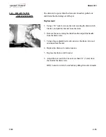
Page 29: ...and out over the arm of the lid 9 Thread the new nylatron strip through the track in the front shroud 10 Lining up the holes in the strips fit the front shroud back over thelidarms 11 Secure the strips to the weight assembly 12 Replace back shroud top cap and lid and replacement is complete ...

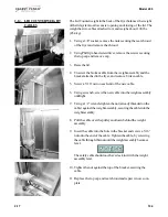
Page 30: ...a 5 16 nut on each end of the new cable 6 Using a wrench screw the new cable into the weight assembly untiltight 7 Using a 1 2 wrench tighten the nut already threaded on the cable againsttheweightassembly securingthecableintothe weightassembly 8 Pull the cable over the pulley and down behind the weight assembly 9 Insert the cable into the hole in the bracket and screw a 5 16 nut onto the end of th...

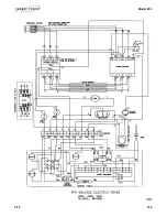
Page 31: ...Model 290 104 2 18 ...

Page 32: ...Model 290 2 19 104 ...

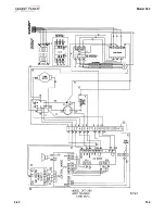
Page 33: ...Model 290 104 2 20 ...

Page 34: ...Model 290 2 21 104 ...

Page 35: ...Model 290 104 2 22 ...

Page 36: ...Model 290 2 23 104 ...

Page 37: ...Model 290 104 2 24 ...

Page 38: ...umber 01100 SerialNumber 0001 Example Voltage 208 3 4 PRICES Your distributor has a price parts list and will be glad to inform you of the cost of your parts order 3 5 DELIVERY Commonly replaced items are stocked by your distributor and will be sent out when your order is received Other parts will be ordered by your distributor from Henny Penny Corporation Normally thesewillbesenttoyourdistributor...

Page 39: ...3 7 CONTROLPANELASSEMBLY 3 5 3 8 BEHIND CONTROLPANELCOMPONENTS 3 6 3 9 FILTER PUMPASSEMBLY SN LG012JC BELOW 3 7A 3 10 FILTER PUMPASSEMBLY SN LG013JC ABOVE 3 7B 3 12 DRAIN VALVE DRAIN SWITCHASSEMBLIES 3 8 3 14 DRAIN PANAND FILTERASSEMBLY 3 9 3 15 CARRIER RACKS JUNCTION BOXASSY 3 10 3 17 3 7 INDEX OF PARTS LIST ILLUSTRATIONS 3 2 104 ...

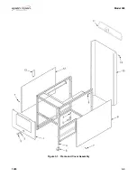
Page 40: ...Model 590 1203 3 3 Figure 3 1 Frame and Cover Assembly ...

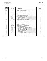
Page 41: ...EG MACHINED 4 5 53673 CASTER SWIVEL 4 2 6 37246 CASTER W BRAKE SWIVEL LOCK 2 7 SC03 005 SCREW 8 x 1 2 PH PHD 4 8 66934 SIDE PANEL RIGHT 1 9 SC01 215 SCREW 5 16 18 x 2 5 HEX HD BOLT 4 10 37291 REAR SHROUD ACCESSASSEMBLY 1 11 35726 TOP COVER REAR SHROUD 1 12 66933 SIDE PANEL LEFT 1 12 14457 KIT SOUND DEADENING 1 13 36337 DOOR ACCESS 1 14 SC02 023 SCREW 8 B x 3 8 PH THD SS 5 3 4 1203 ...

Page 42: ... ELEMENT SHORT 5 4 SC01 074 SCREW 10 32 x 1 2 PH THD S As Required 5 35435 BRACKET HI LIMITPROBE 3 6 35462 BRACKET HI LIMITPROBE 3 7 35234 HEAT ELEMENTASSEMBLY 8 5 KW208V 2 35598 HEAT ELEMENT 8 5 KW 240V 2 48367 HEATELEMENT 230V Int l Only 2 36290 HEATELEMENT 220V Int l Only 2 8 16855 SEAL O RING 4 9 WA01 005 WASHER 5 8 DIA TYPEA SERIES N 8 10 NS01 017 NUT 5 8 18 B HEX 4 ...

Page 43: ...1 010 WASHER 3 8 SPLIT RING SS 10 5 35092 CARRIAGE 1 6 SC01 069 SCREW 3 8 16 X 1 1 2 HEX HD S2P 8 7 36839 SLIDE 2 8 SC01 042 SCREW 3 8 16 X 1 HEX C 2 9 36625 WELD ASSEMBLY C W CARRIAGE 1 10 36627 COUNTERWEIGHT BAR 4 11 36626 SPACER C W FRAME 2 12 37362 WHEEL CARRIAGE 4 13 37363 SPACER CARRIAGE WHEEL 4 14 37364 SPINDLE 4 15 SC01 081 SCREW 3 8 24 X 3 4 HEX HD SS 4 ...

Page 44: ... 1 3 51531 Stop Lid Cast 1 4 SC01 041 Screw 5 16 18 x 1 HEX HD C 2 5 55754 HandleWeldAssembly 1 6 55756 Assy Latch Sleeve Coat 1 7 59169 Lid Latch Bracket 1 7a 52498 Spring Lid Latch 1 7b 51707 Lid Latch Bracket 1 8 SC01 248 Screw 10 32 x 1 25 PH THD SS 2 9 65817 Weldment 290 Lid 1 Figure Item No Part No Description Qty ...

Page 45: ...90 3 8 104 Figure Item No Part No Description Qty 3 5 CONTROLPANELASSEMBLY 1 55848RB CONTROLASSY KFC 290 SMS 1 2 50624 CONTROL DECAL 8 HEAD KFC 1 3 61748 MENU CARD 1 4 NS02 005 NUT 4 5 51877 WIRE SPEAKERASSY 1 ...

Page 46: ...SSY 240V E M HEAT CONTACTOR CE 240V UK 1 1 65074 ASSY 240V E M HEAT CONTACTOR CE 230V 1 2 29901 CAPACITOR RESISTORASSY 1 3 19405 CONTACTOR KIT 208 240 VAC 1 4 17216 BRACKET ASSY HIGH LIMIT 1 5 16738 450 F HIGH LIMIT 1 6 18364 FUSE HOLDERASSY 15AMP 2 6 EF02 006 FUSE HOLDER 2 6 EF02 007 FUSE 15 AMP 2 7 14329 PROBE KIT 1 1 2 3 4 5 6 7 notshown ...

Page 47: ...Model 590 3 7A FILTER PUMPASSEMBLY SN LG012JC BELOW 3 10 1203 Pump Interior ...

Page 48: ...1 2 MALE ELBOW 2 11 46854 MOTOR FILTER PUMP 1 12 62206 ASSY TUBE PUMP TO DISCON 590 1 13 17430 UNION MALE FITTING 1 14 16807 FITTING CONNECTOR MALE 1 15 FP01 122 REDUCER 3 8 TO 1 2 1 16 FP02 024 NIPPLE CLOSE 3 8 1 17 35472 CHECK VALVE PRESSURE 1 18 FP02 007 NIPPLE 3 8 X 1 1 2 1 19 17437 PUMP SUBASSY 8GPM 1 20 17454 BODY PUMP 1 21 17456 PUMP SHIELD 2 22 17451 COVER PUMP 1 23 SC01 016 PLUG 1 4 HEX C...

Page 49: ...Model 590 3 7B FILTER PUMPASSEMBLY SN LG013JC ABOVE 3 12 1203 Pump Interior ...

Page 50: ...E 3 4 TUBE 3 4 NPT 2 11 46854 MOTOR FILTER PUMP 1 12 FP01 089 BUSHING REDUCING 3 4M TO 1 2F 1 13 17407 CONNECTOR 1 2 MALE ELBOW 1 14 62206 ASSY TUBE PUMP TO DISCON 1 15 17430 UNION MALE FITTING 1 16 21800 VALVE 3 4 CHECK 1 17 FP02 021 NIPPLE 3 4 NPT X 3 IN LG BL 1 18 64218 PUMP SUBASSY 8GPM 1 19 SC01 132 1 4 20 X 5 8 SOC HD CAP SCREW 4 20 23469 ROLLER 7 GPM PUMP 5 21 23468 ROTOR 7GPM PUMP 1 22 236...

Page 51: ...G012JC BELOW 1 1 66553 DRAIN VALVEASSEMBLY SN LG013JC ABOVE 1 2 SC01 058 SCREW 6 32 X 1 PH PAN HD 2 3 WA01 006 WASHER 6 TYPEA 2 4 54228 DRAIN SWITCH W BOOT 1 5 NS02 005 NUT 6 32 HEX 2 6 52519 CORDASSY DRAIN INTERLOCK 1 7 65522 BRACKET SWITCH BEFORE DEC 29 2003 1 7 67220 BRACKET SWITCH AFTER DEC 29 2003 1 8 EF02 017 STRAIN RELIEF 2 ...

Page 52: ...Model 590 1203 3 15 3 9 DRAIN PAN AND FILTER ASSEMBLY ...

Page 53: ...17502 TOP FILTER SCREEN 1 10 36505 WASHER STANDPIPE 1 11 24212 STANDPIPE ASSEMBLY 1 12 17431 UNION MALE FITTING 1 13 17432 UNION HANDLE FITTING 1 14 24211 WELDMENT FILTER TUBE AND WASHER 1 15 23740 HANDLE STANDPIPE 8 HEAD 1 16 SC01 045 SCREW 10 32 X 1 2 3 17 23804 INSERT FILTER NUT 1 18 OR01 007 O RING FILTER NUT INSERT 1 19 23803 FILTER NUT S N AH086JB HIGHER 1 19 55877 FILTER NUT S N KH031JJ LOW...

Page 54: ...ARRIERASSY 1 2 44782 RACK HALF SIZE 8 HEAD FRYER 5 3 62126 JUNCTION BOXASSY 1 3 62127 JUNCTION BOX ASSY CE 1 4 62106 JUNCTION BOX MACHINED 1 5 51057 ASSY EMC FILTER CE 1 6 SC01 023 SCREW 6 32 X 1 4 PH RHD C 8 7 36719 CORD MAIN POWER 1 8 62181 BASKET OPTIONAL 4 9 21519 COVER WIRE RACK OPTIONAL 4 notshown ...

Reviews: