45
3
3..1
18
8 IIn
nffo
o &
& F
Fiilltte
err B
Bu
utttto
on
n S
Stta
attss
NOTE: If no buttons are pressed within 5 seconds in any of stats modes, the controls
revert back to normal operation.
3
3..1
18
8..1
1 IIn
nffo
o B
Bu
utttto
on
n S
Stta
attss
T
Ta
ab
blle
e 3
3--4
4 IIn
nffo
o B
Bu
utttto
on
n S
Stta
attss
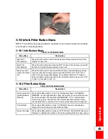
Menu Step
Description
Actual Oil
Temperature
Press the info button 1 time and the actual oil temperature shows in the
display for each vat.
Set-Point
Temperature
Press the info button two times and “SP” shows in the display, along with
the set-point (preset) temperature of each vat.
Recovery Infor-
mation For Each
Vat
Press the info button 3 times and REC shows in the left display and the
recovery time that oil temperature went from 250°F (121°C) to 300°F
(149°C) shows in the right display. For example, “REC 5:30” means it
took 5 minutes and 30 seconds for the oil temperature to recover to 300°
F (149°C) from 250°F (121°C).
3
3..1
18
8..2
2 F
Fiilltte
err B
Bu
utttto
on
n S
Stta
attss
T
Ta
ab
blle
e 3
3--5
5 F
Fiilltte
err B
Bu
utttto
on
n S
Stta
attss
Menu Step
Description
Cook Cycles Re-
maining Before
Filtering
Press either filter button 1 time. The left display shows “COOKS RE-
MAINING” and the right display shows the number of cook cycles before
the next auto filter. For example, “REMAINING” “3” “6”, means after 3
more cook cycles on the left vat, the controls asks the operator if they
are ready to filter or not. But, 6 more cook cycles remain on the right vat.
Time & Date
Press either filter button 2 times, “FILTERED” shows in the displays,
along with time-of-day and date of the last filter.
Hours of Usage
Press either filter button 3 times and “FLTR PAD” “XX HOURS” shows in
displays to indicate the number of hours the existing filter has been used.
Summary of Contents for Wendy's Evolution Elite EEG-251
Page 2: ......
Page 5: ...Contents iii...
Page 14: ...Introduction 2...
Page 19: ...Installation 7 Figure 2 1 Flexible Gas Line Cable Restraint Installation...
Page 22: ...Figure 2 2 1 Well Dimensions Figure 2 3 2 Well Dimensions Installation 10...
Page 23: ...Figure 2 4 3 Well Dimensions Figure 2 5 4 Well Dimensions Installation 11...
Page 24: ...Installation 12...
Page 51: ...Operation 37...
Page 62: ...Operation 48...
Page 68: ...Information Mode 54...
Page 72: ...Product Program Mode 58...
Page 87: ...Troubleshooting 73...
Page 88: ...Troubleshooting 74...
Page 89: ...blank page...


