11
Henrad CC FF
- Installation
GENERAL
7. Thermostatic radiator valves.
Caradon Plumbing Limited support the
recommendations made by leading manufacturers of
domestic heating controls that heating systems utilising
full thermostatic radiator valve control of temperature in
individual rooms should also be fitted with a room
thermostat controlling the temperature in a space served
by radiators not fitted with such a valve. Such an
arrangement will provide for a more efficient control of the
environment and will also avoid the continuous running of
the circulation pump during programmed heating ON
periods, saving electrical energy.
IMPORTANT
It is therefore strongly recommended that, when
thermostatic radiator valves are used, the space heating
temperature control over a living/dining area or a hallway,
having a heat requirement of at least 10% of the boiler
output, is achieved using a room thermostat whilst other
rooms are individually controlled by thermostatic radiator
valves.
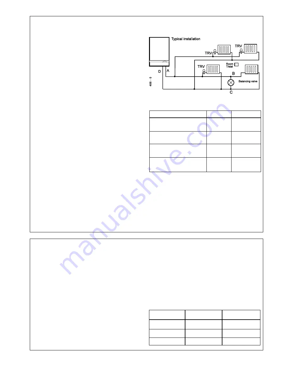
However, if thermostatic radiator valves are fitted to all
radiators then a bypass MUST be fitted. This should
consist of 22mm (
3/4
") pipe positioned as far from the
boiler as possible and incorporating a balancing valve
which cannot be adjusted by the householder.
For adjustment refer to Frame 45.
a.
The total length of pipework A, B, C & D
MUST NOT be
less than 3m (10') and must not include any other
valves.
b.
The balancing valve MUST be at least one turn open.
8. Hydraulic resistance
Having subtracted the hydraulic resistance of the boiler
the head available to overcome system resistance at
MAXIMUM CENTRAL HEATING OUTPUT, with an 11
0
C
(20
0
F) temperature differential, is shown in the table.
5
SEALED SYSTEM REQUIREMENTS - Central Heating - continued
CC 80 FF
CC 100/120 FF
Max CH Output
kW
17.6
23.4
(Btu/h)
(60 000)
(80 000)
Water flow rate
l/sec
0.382
0.508
(gal/min)
(5.04)
(6.7)
Temperature
o
C
11
11
differential
(
o
F)
(20)
(20)
Head available for
m.w.g.
2.75
2.5
system pump, pos.3 (ft.w.g.)
(9.0)
(8.0)
Water Flow Rate and Pressure Loss
9. Draining the system
Draining taps MUST be located in accessible positions
to permit the draining of the whole central heating
system, including the central heating side of the boiler.
The taps should be at least
1/2
" BSP nominal size and
be in accordance with BS 2879. The boiler flow and
return service valves (fitted to the piping frame) have
drain plugs to drain the BOILER ONLY, in the event of
the system drain tap being unable to do so.
6
DOMESTIC HOT WATER REQUIREMENTS
A filter is provided for fitting to the DHW inlet connection. This
is primarily for NEW BUILD HOUSING systems.
Refer to the adjoining table for the minimum DYNAMIC inlet
water pressure required to achieve maximum boiler output for
the CC 100 FF and CC 120 FF.
6. Hard water areas
In areas where the water is 'hard' it is recommended that a
proprietary scale-reducing device is fitted into the boiler
cold supply, within the requirements of the local water
company.
1. The domestic hot water service must be in accordance with
BS 5546 and BS 6700.
2. For the minimum and maximum working pressures of the
CC FF domestic hot water circuit refer to Table 1, page 3.
However in areas where DHW inlet pressures are greater
than 2 bar a water pressure governor should be fitted to
ease commissioning
3. The cold water supply pipe should be flushed before fitting
the boiler.
It is the responsibility of the installer to ensure that the DHW
inlet is free from debris.
4. The boilers are suitable for connection to most types of
washing machine and dishwashing appliances.
5. When connecting to suitable showers, i.e. those designed
for modulating domestic hot water, ensure that:
a.
The cold inlet to the boiler is fitted with an approved anti-
vacuum or syphon non-return valve.
b.
Hot and cold supplies are of equal pressure.
Boiler
with filter fitted
without filter fitted
Response 80
1.0 bar
0.5 bar
Response 100
1.2 bar
0.7 bar
Response 120
1.2 bar
0.7 bar
Summary of Contents for CC 100 FF
Page 1: ......


