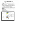
A
(Inch)
H
(Inch)
B
(Inch)
D
(Inch)
WEIGHT
(lb)
POLE
C
ODE
BOL
L
ARD
CODE
7
3
/
32
10'
20
15
/
32
2
3
/
4
53,2 lb
PAFD.R03.T001
LL2042.681
7
3
/
32
13'
20
15
/
32
2
3
/
4
65,3 lb
LL2042.681
7
3
/
32
10'
20
15
/
32
2
3
/
4
56,2 lb
LL2042.682
7
3
/
32
13'
20
15
/
32
2
3
/
4
68,3 lb
LL2042.682
7
3
/
32
10'
20
15
/
32
2
3
/
4
59,1 lb
LL2042.683
7
3
/
32
13'
20
15
/
32
2
3
/
4
71,2 lb
LL2042.683
7
1.
2.
8
1.
9
1 lb ft
10
3.
2.
1.
4xM6 Countersunk Bolts
S4
1xM4 Cross Slotted
Bolts
3.
2.
S2,5
3.
4xM4 Cross Slotted
4xM4 Lock Washers
1.
2.
3.
4.
2xM4 Countersunk Bolts
4xM5 Round Head Bolts
5.
S2,5
S3
2xM4 Countersunk Bolts
1xM4 Lock Washers
6 lb ft
2 lb ft
2 lb ft
3 lb ft
ASSEMBLY INSTRUCTIONS
English
To install the product on the floor;
1.
. The floor on which the product will be installed must be fla
2.
. The space on the floor is adjusted according to the concrete dimensions give
2.1. In order to align the connection holes of the product, the anchor plate is placed as in the
picture.
2.2. The anchor plate is mounted to the studs coming out of the concrete with the help of
washers
and nuts. (4 pieces, M12 washers and 4 pieces, M12 nuts).
Note: When the studs are fixed after the concrete is laid, the anchor plate for alignment
is removed.
3.. Mounting the pole to the groun
3.1. M12 Nut and M12 Washer are mounted on anchor studs for direct vertical adjustment,
respectively. (4 pcs, M12 Nuts and 4 pcs, M12 Washers).
3.2. The post is placed on the M12 Washers with the studs aligned.
3.3. The pole is mounted to studs coming out of concrete with the help of washers and nuts with
60lb ft
torque. (4 Pieces, M12 Washers and 8 Pieces, M12 Nuts).
Note: Before the nuts are fixed, the verticality of the pole should be adjusted.
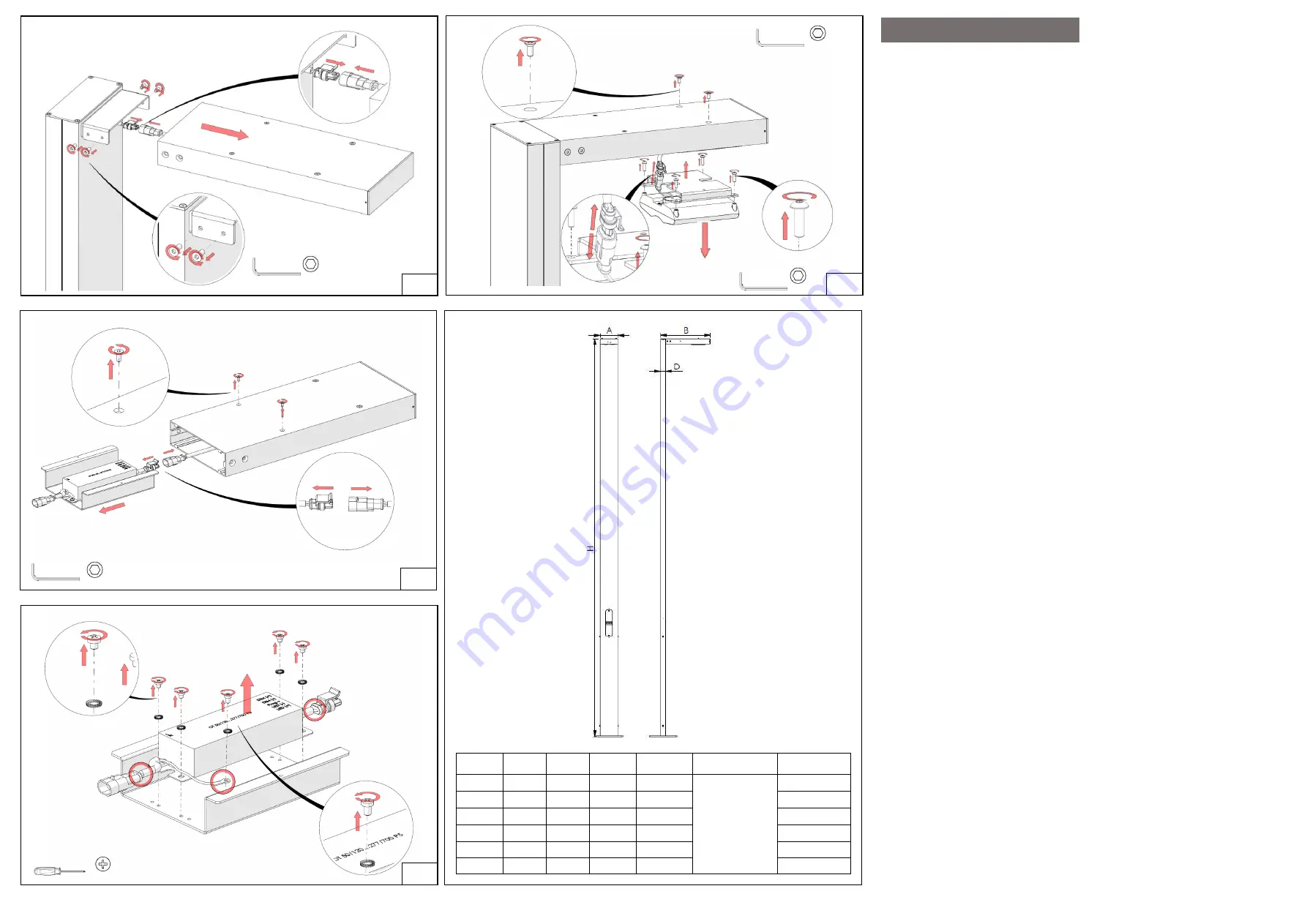
4.
. Mounting the luminaire to the pol
e
4.1.M6 knurled washer is thrown under the pole connection plate and the pole is mounted
with
7 lb ft
torque with M6 Imbus bolts. (2 Pieces M6 Serrated Washers and 2 Pieces M6
Imbus Bolts)
4.2. The cable coming from the fuse and the cable coming out of the product are assembled
with the
help of a socket.
4.3. The luminaire is placed on the pole so that the connection plate is inside.
4.4. The countersunk Imbus bolts for fixing the luminaire to the connection plate are
tightened
with
7 lb ft
torque (4 pieces, M6 Countersunk Imbus Bolts).
5.
. Installation of the power cable coming from the outer lin
5.1. The countersunk Imbus bolts holding the fuse cover are removed (2 pieces, M4
Countersunk Imbus Bolt).
5.2. The insurance cover is removed.
5.3. The power cable coming from the external line is mounted.
Note: While mounting the fuse cover to its place, the countersunk Imbus bolts are tightened
with a torque of
1.84lb ft
(2 pieces, M4 Countersunk Imbus Bolts).
6.
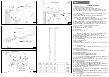
The pole and the armature are ready to use.To replace the LED driver;
7.
Note: Before
starting this process, the electrical connection to the product must be disconnected.
8.
. Removing the luminaire from the pol
e
7.1. The countersunk-head imbus bolts for fixing the luminaire to the connection plate are
removed (4
pieces, M6 Countersunk Imbus Bolts).
Note: After the LED driver replacement is completed, these bolts are tightened with
6 lb ft
torque (4 pieces, M6 Countersunk Bolt).
7.2. The armature is pulled slowly forward. Note: While doing this, make sure that the cable coming
from the pole is not damaged.
7.3. The socket that connects the cable coming from the fuse and the cable coming out of the product
are separated from each other.
8.. To remove the cartridge grou
8.1. The grub screws holding the cartridge group are loosened sufficiently.
Note: Bolts do not need to be completely removed. After the process is completed, the
cartridge group plate is aligned and the setscrew bolts are tightened until the bolt heads are aligned with
the side surface of the armature.
8.2. The cartridge group is removed slowly.
Note: While doing this, be careful not to damage the cable coming from the LED modules.
8.3. The socket that connects the cable coming from the LED module and the cable coming from the
LED driver are separated from each other.
9.
9.LED driver remova
9.1. The star cylindrical head bolt holding the grounding cable is removed.
9.2. The star cylindrical head bolts holding the LED driver are removed.
9.3. The LED driver is removed.
Note 1: While removing the cartridge group, care should be taken not to damage the electrical
connections inside the product. This should be done sensitively.
Note 2: After the LED driver replacement is completed, the cartridge group is put into place,
knurled washers are placed and the star cylindrical head bolts are tightened with a torque of
0.7lb ft
(5 pieces, M4 Knurled Washers and 5 pieces, M4 Star Cylindrical Head Bolts).
To replace the LED lighting module;
10.
0. To remove the LED lighting modu
10.1.LED lighting module are removed (2 pieces, M4 Countersunk Head Imbus Bolts).
Note: After the replacement of the LED lighting module is completed, it is tightened with a
torque of
1.84 lb ft
with countersunk bolts (2 pieces of M4 Countersunk Imbus Bolts).
Note: Take precautions by holding the LED lighting module while it is unloaded to avoid
damaging the cables.
10.2. Pull the LED lighting module down gently.
Note: Be careful not to damage the cables while doing this.
10.3. Separate the connector that connects the cable coming from the LED driver and the cable coming
from the LED lighting module.
10.4 Remove the round head Imbus bolts that hold the LED lighting module connection sheet (4 pieces,
M5 Round Head Imbus Bolts).
Note: After the replacement of the LED lighting module is completed, the module connection
plate is placed in its place and the round head imbus bolts are tightened with
4.5lb ft
torque (4 pieces,
M5 Round Head Imbus Bolt).
10.5.LED lighting module and module connection plate are separated from each other.


