Chapter 5 Wheels, Tires & Brakes
V-4
Handlebar
REMOVAL
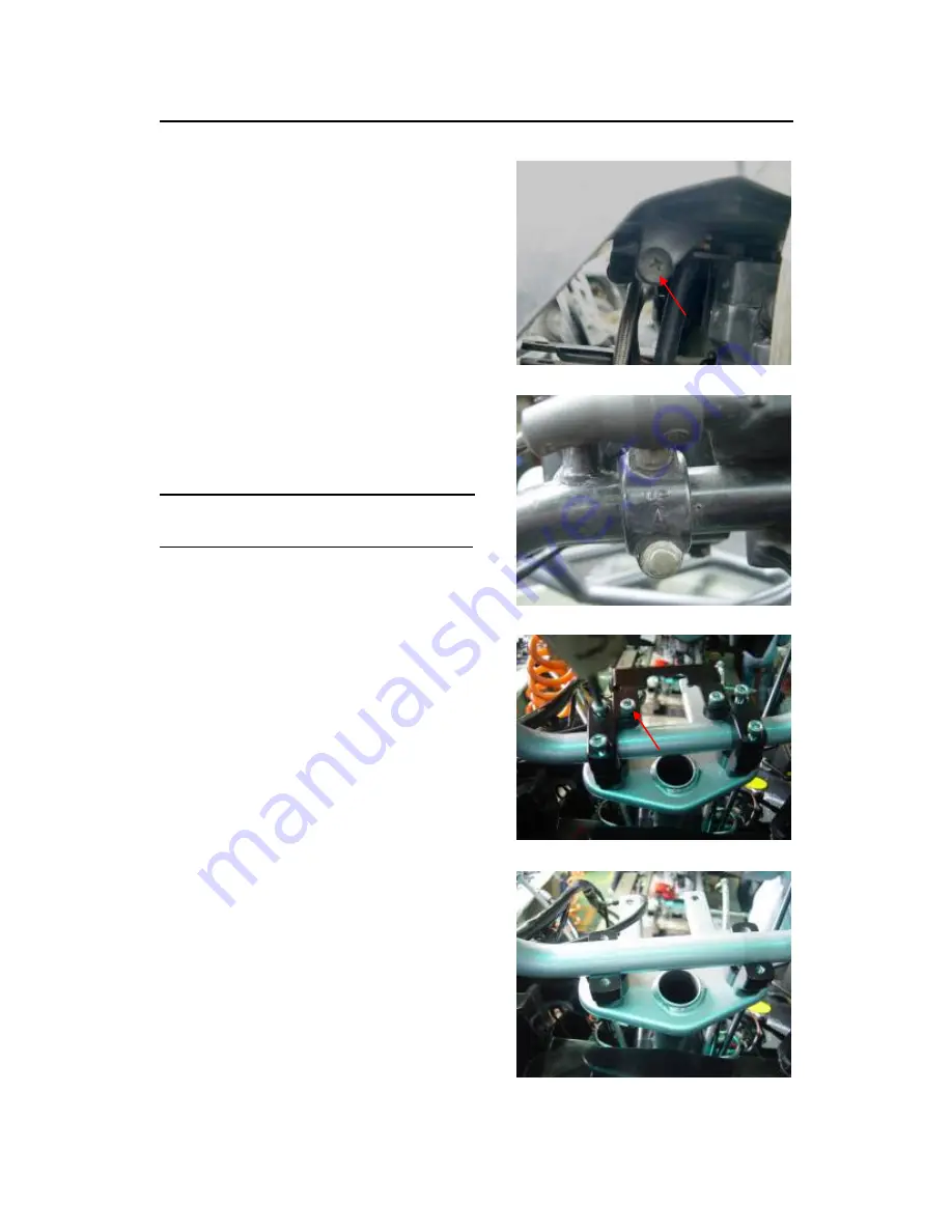
Remove the speedometer assembly mounting
screws.
Loosen L/R hand brake master cylinder holder
mounting bolts and remove brake cylinder from
handlebar.
Loosen L handle switch mounting bolts and
remove switch from handlebar.
Disconnect brake switch wire, overdrive switch
wire, throttle and choke cable.
Loosen four handle clamp hex socket bolts and
remove handlebar.
NOTE
◦
Do not remove the brake hose bolt from the
brake cylinder.
INSTALLATION
Install handlebar onto lower holders and aligning
the punch mark on the handlebar with the upper
surfaces surface of the lower holders.
Install the handlebar upper holders and tighten
four hex socket bolts.
Torque: 24-30 N.m (17-22 ft.lb)
Install the L/R hand master cylinder holder with
the UP mark facing up and aligning the end of
the holder with the punch mark on the handlebar.
Tighten the upper bolt first, then tighten the lower
bolt.
Torque: 24-30 N.m (17-22 ft.lb)
Install the L handle switch housing aligning the
locating pin on the housing with the hole in the
handlebar.
Connect the throttle and choke cable.
Connect the brake switch and overdrive wire.
Insert speedometer assembly to the handlebar
and tighten the mounting screw.
Summary of Contents for 2002 ATV-320 S
Page 14: ...Chapter 1 Engine Transmission Gear I 5 Cylinder Head Cover 1 5 2 3 7 6 4 8 11 10 9 5 5 5 9...
Page 15: ...Chapter 1 Engine Transmission Gear I 6 Cylinder Head 2 3 4 4 5 6 7 8 9 11 10 12 12 13 14 18...
Page 16: ...Chapter 1 Engine Transmission Gear I 7 Camshaft Valve Cam...
Page 29: ...Chapter 1 Engine Transmission Gear I 20 Cylinder Piston Crankshaft...
Page 36: ...Chapter 1 Engine Transmission Gear I 27 Crankcase...
Page 40: ...Chapter 1 Engine Transmission Gear I 31 Right Crankcase Cover...
Page 42: ...Chapter 1 Engine Transmission Gear I 33 Cooling system...
Page 47: ...Chapter 1 Engine Transmission Gear I 38 Left Crankcase Cover...
Page 54: ...Chapter 1 Engine Transmission Gear I 45 Transmission...
Page 61: ...Chapter 2 Fuel System Carburetion II 3 3 CARBURETOR...
Page 65: ...Chapter 2 Fuel System Carburetion II 7 7 FUEL TANK...
Page 68: ...Chapter 2 Fuel System Carburetion II 10 10 AIR CLEANER ASSEMBLY...
Page 70: ...Chapter 2 Fuel System Carburetion II 12 12 EXHAUST SYSTEM...
Page 78: ...Chapter 3 Ignition and Starting System III 7 Recoil Backup Starting System...
Page 81: ...Chapter 4 Frame Cover IV 2 FRAME BODY 320S...
Page 82: ...Chapter 4 Frame Cover IV 3 FRAME BODY 320U...
Page 83: ...Chapter 4 Frame Cover IV 4 BODY COVER SEAT 320S...
Page 84: ...Chapter 4 Frame Cover IV 5 BODY COVER SEAT 320U...
Page 91: ...Chapter 5 Wheels Tires Brakes V 2 HANDLE BAR...
Page 92: ...Chapter 5 Wheels Tires Brakes V 3 STEERING MPH...
Page 95: ...Chapter 5 Wheels Tires Brakes V 6 FRONT REAR WHEEL...
Page 98: ...Chapter 5 Wheels Tires Brakes V 9 FRONT SUSPENSION...
Page 99: ...Chapter 5 Wheels Tires Brakes V 10 REAR SUSPENSION SWING ARM SUB ASS Y...
Page 103: ...Chapter 5 Wheels Tires Brakes V 14 HYDRAULIC BRAKE SYSTEM...
Page 104: ...Chapter 5 Wheels Tires Brakes V 15 BRAKE CALIPER...
Page 114: ...Chapter 6 Alternator Electrical Equipment VI 2 Alternator Starter Gear...
Page 125: ...Chapter 6 Alternator Electrical Equipment VI 13 Wire Diagram...


