background image

Table of contents

5

Table of contents

General Information ....................................6

1.1 

Intended use ................................................. 6

1.2 

Exploded view ............................................... 8

1.3 

Wear parts ..................................................... 8

1.4 

Technical data ............................................... 9

1.4.1 

Model designation ......................................... 9

1.4.2 Impellers ........................................................ 9

1.4.3 Installation ..................................................... 9

1.4.4 

Shaft sealing ................................................. 9

1.4.5 Drive ............................................................ 10

1.4.6 

Dimensions, weights, performance data ..... 10

1.4.7 

General data ............................................... 10

2 Safety .........................................................12

2.1 Notes/explanations...................................... 12

2.1.1 

Machine identification.................................. 12

2.2 

Integrated safety systems (optional) ........... 13

2.3 

Connections on the pump ........................... 14

2.4 

Safety measures ......................................... 14

2.5 

Obligations of the operating company......... 14

General Hazard Warnings ........................16

3.1 Dangers....................................................... 16

3.2 

Danger zones on the pump ......................... 16

3.3 

Assembly, operation and maintenance 

personnel .................................................... 16

3.4 

Installation of replacement parts and wear 

parts ............................................................ 16

3.5 

Shut-off procedures ..................................... 17

4 Transport ....................................................18

4.1 

Scope of delivery......................................... 18

4.2 

Transport and packaging ............................ 18

4.2.1 

Delivery (including spare parts and re-

placement parts) ........................................... 18

4.2.2 

Intermediate storage ................................... 18

4.3 

Transportation to the site of installation 

(by the customer) ........................................ 18

4.3.1 

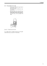
Transportation with a forklift truck ............... 18

4.3.2 

Transportation with a crane ......................... 19

5 Installation/Fitting .....................................20

5.1 Installation ................................................... 20

5.2 Dimensions ................................................. 21

5.3 

Technical data ............................................. 22

5.4 

Electrical connection ................................... 22

5.5 

Motor protection .......................................... 22

5.6 

Direction of rotation check........................... 47

5.6.1 

Changes in direction of rotation .................. 24

5.7 

Motor connection diagrams ......................... 24

5.7.1 

PTC thermistor connection.......................... 24

5.8 

Frequency converter operation ................... 24

5.9 

Laying the pipelines .................................... 25

5.10 

Frost protection ........................................... 25

6 Commissioning .........................................26

6.1 

Operating modes and connecting frequen-

cy .................................................................26

6.2 

Starting up ................................................... 27

7 Maintenance/Cleaning ..............................28

7.1 Maintenance................................................ 28

7.2 

Maintenance instructions during prolon-

ged periods of inactivity............................... 29

7.3 

Bearing lubrication ...................................... 29

7.4 Seals ........................................................... 30

7.5 Cleaning ...................................................... 30

7.6 

Cleaning the filter strainer ........................... 31

7.7 

Tightening torques for nuts and bolts .......... 32

7.8 Disposal ...................................................... 32

Disturbance/Cause/Trouble Shooting ..... 33

9 Disassembly/Assembly ............................35

9.1 Disassembly ................................................ 35

9.2 Assembly ..................................................... 37

Table of figures

Figure 1 

Exploded view ............................................... 8

Figure 2a  Name plate (standard) ................................ 13

Figure 2b  Name plate (explosion protection pump) .... 13

Figure 3 

Connections on the pump  .......................... 14

Figure 4 

Transporting with a crane ............................ 19

Figure 5 

Dimensions ................................................. 21

Figure 6 

Dry running label ......................................... 29

Summary of Contents for 25-110/0032 WX

Page 1: ...tegrated filter Operating manual Translation of the original operating manual Herborner Pumpentechnik GmbH Co KG Littau 3 5 DE 35745 Herborn Phone 49 0 27 72 933 0 Fax 49 0 27 72 933 100 E mail info herborner pumpen de www herborner pumpen de A WX37 GB ...

Page 2: ... the translated text refe rence should be made to the original operating manual Ger man for clarification or the manufacturer is to be contacted Copyright The transfer and duplication of this document and utilisation and communication of its content is prohibited unless expli citly stated otherwise Non compliance with this stipulation will result in compensation for damages All rights reserved ...

Page 3: ...by declare that the Close coupled centrifugal pump UNIBLOCK WX complies with all the pertinent provisions of EC Machinery Directive 2006 42 EC The machine also complies with all pertinent provisions of the following EC directives Directive 2014 30 EU Directive 2014 34 EU for explosion protection version Original Herborner Pumpentechnik GmbH Co KG Littau 3 5 DE 35745 Herborn Phone 49 0 27 72 933 0 ...

Page 4: ......

Page 5: ... 1 Transportation with a forklift truck 18 4 3 2 Transportation with a crane 19 5 Installation Fitting 20 5 1 Installation 20 5 2 Dimensions 21 5 3 Technical data 22 5 4 Electrical connection 22 5 5 Motor protection 22 5 6 Direction of rotation check 47 5 6 1 Changes in direction of rotation 24 5 7 Motor connection diagrams 24 5 7 1 PTC thermistor connection 24 5 8 Frequency converter operation 24...

Page 6: ...1 1 Intended use The close coupled centrifugal pump with integrated filter UNIBLOCK WX is particularly suitable for pumping and filtering cutting coolant and other fluids containing coarse contaminants that are used in industrial plants Each pump is solely intended for the purpose previously specified Any other application or applications extending beyond the stated purpose or alterations made to ...

Page 7: ...ally fatal explosive atmosphere Comply with the limit values The explosion protection marking on the pump refers only to the pumping component The motor has its own explosion protection marking The explosion proof centrifugal pumps satisfy the require ments of electrical equipment for use in potentially explosive atmospheres in accordance with Directive 94 9 EC of the European Council dated 23 Mar...

Page 8: ...or shaft 831 Fan 832 Fan hood 903 1 Screwed plug 903 2 Screwed plug 903 3 Screwed plug 920 Nut 940 Key 1 3 Wear parts The specifications relating to the selection of wear parts are based on the initial demand for two year operation in accordance with DIN 24296 Wear parts Number of pumps if available 1 2 3 4 5 6 7 8 9 10 Impeller 1 1 1 1 2 2 2 20 suction cover 1 1 1 1 2 2 2 20 Mechanical seal set 1...

Page 9: ...e from CuSn10 C pump casing made from EN GJL 250 with epoxy resin hot powder coating Construction Standard S Special construction 1 4 2 Impellers Open multi vane impellers are used for pumped media with light contamination and to provide operationally safe pumping 1 4 3 Installation The pumps are delivered in vertical installation Vertical installation of the pump For operational safety reasons it...

Page 10: ...losion protection a tolerance of 5 also applies for the voltage range Motor data Design IM B5 Motor connection Manufacturer specific Protection type IP 55 Speed 3000 3600 rpm Frequency 50 60 Hz Connection 2 2 kW 230 5 400 3 460 3 V Connection 3 0 kW 400 5 690 3 460 5 V Insulation class VDE 0530 Customer specific solutions may differ from this standard data 1 4 6 Dimensions weights performance data...

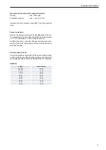
Page 11: ...tudes 1000 m above sea level A different density or viscosity changes the hydraulic perfor mance of the pump Pay attention to the motor performance with these media Sound pressure level The sound pressure level dB A of the pump during cavitati on free operation lies within the range of Qopt and is below the limit values specified in EC Directive 98 37 EC for machines 50 60 Hz P2 kW 3000 3600 rpm 0...

Page 12: ...mportant This indicates tips for usage and other par ticularly useful information It is not a signal word for a dangerous or hazardous situation 2 1 1 Machine identification The information contained in this operating manual is only applicable to the pump that is indicated on the title page Stick the supplied pump name plate into the operating manu al or on the control panel This will ensure that ...

Page 13: ...ering spare parts please make sure you specify the pump type and the order number Also observe additional name plates on the motor The name plate is attached to the fan hood 10 CE mark 11 Year month of manufacture 12 Explosion protection marking for explosion protection pumps only 13 Explosion protection symbol for explosion protection pumps only 2 2 Integrated safety systems optional Check the in...

Page 14: ...ted specific directives and particu larly the directive 89 655 EEC concerning the minimum requirements for the protection of the health and safety of workers when using equipment at work and occupational safety regulations 2 3 Connections on the pump Figure 3 Connections on the pump The following connections are located on the pump 1 Inlet connecting flange 2 Outlet connecting flange 3 Electric co...

Page 15: ...ccident preven tion regulations the safety of operating equipment protec tive equipment and maintenance product disposal waste management legislation material disposal waste management legislation cleaning cleaning agents and their dispo sal and relevant environmental constraints Connections Observe local regulations e g for electrical connections when carrying out fitting installation and commiss...

Page 16: ...ouble shooting of the pump 1 Only trained and authorised persons are allowed to install and operate the pump 2 Clearly define and observe responsibili ties when operating the pump 3 Observe the shut off procedures speci fied in the operating manual when car rying out all work processes operation maintenance repair etc 4 The operator should not impair the safety of the pump 5 The operator must ensu...

Page 17: ...d with before conducting any maintenance cleaning and or repair work by specialists only Warning Electric current can result in fatal injury Disconnect the block motor 802 according to the 5 safety rules When cleaning close any electrical cabinets that are open to prevent dust or water from entering ...

Page 18: ...t truck The forklift must be designed to support the weight of the pump The driver must be authorised to operate the forklift truck 4 Transport 4 1 Scope of delivery The detailed scope of delivery is in the order confirmation 4 2 Transport and packaging The pumps are carefully checked and packed before being shipped However damage in transit cannot be ruled out 4 2 1 Delivery including spare parts...

Page 19: ...5 2 Dimensions 4 3 2 Transportation with a crane The crane must be able to support the full weight of the pump The operator must be authorised to ope rate the crane Attach the pump to the crane at the spe cified attachment points using appropriate separate lifting accessories e g cross bar stop belt ropes etc and transport the pump ...

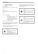
Page 20: ... leakage The seals must be resistant to the pumped medium When setting up the pump outdoors erect a protective shelter to protect it from atmospheric influences Caution Impermissible heating will damage the three phase motor Ensure there is an adequate supply of cooling air during operation To prevent vibrations being transmitted to the building and the pipeline system it is advisable to install p...

Page 21: ... 32 191 0302 WX 65 32 570 485 142 170 198 215 302 270 330 170 210 185 320 59 74 32 191 0402 WX 65 32 635 485 142 170 220 215 302 270 330 170 210 185 320 59 84 40 161 0112 WX 65 40 475 475 139 150 156 215 302 270 330 170 210 185 320 59 59 40 161 0152 WX 65 40 510 475 139 150 176 215 302 270 330 170 210 185 320 59 59 40 161 0222 WX 65 40 535 475 139 150 176 215 302 270 330 170 210 185 320 59 62 40 1...

Page 22: ...with DIN VDE 0165 in potentially explosive atmospheres The earth neutral connection residual current circuit brea ker etc must correspond to the directives of the local public utility com pany PUC and function flawlessly according to the electrician s inspection The cross section and voltage drop of the supply line must comply with the respective regulations Caution Impermissible heating will dama...

Page 23: ...nd may damage the pump Danger The rotating impeller can cut or crush people s hands and arms Secure the pump when checking the direction of rotation Do not reach into the pressure flanges or the intake port of the pump casing Danger Risk of a potentially fatal explosion during the installation phase Provide a constant supply of pumped media to the supply and pressure pipes as well as to the interi...

Page 24: ...es can arise due to the differences in motor manufacturer and size Pay attention to the documents accompanying the motor and the information in the terminal box cover 1 2 A1 A2 W2 U2 V2 L1 L2 L3 U1 V1 W1 W2 U2 V2 L1 L2 L3 U1 V1 W1 W2 U2 V2 L1 L2 L3 U1 V1 W1 W2 U2 V2 L1 L2 L3 U1 V1 W1 W2 U2 V2 L1 L2 L3 U1 V1 W1 W2 U2 V2 L1 L2 L3 U1 V1 W1 3 5 5 5 3 3 Operating voltage Operating frequency 400 690V 5 ...

Page 25: ...pelines Lay the pressure pipes in accordance with the applicable regulations and relevant accident prevention regulations Warning Escaping hot pumped media is poten tially fatal Do not exceed the pipeline forces Ensure measures are in place for complete ventilation during the laying procedure Pressure pipe lay frost free secure and connect so they are stress free Pipe forces and moments must not a...

Page 26: ...er Take precautionary measures to pre vent burning Caution Dry running the pump will destroy the mechanical seal Before starting the pump fill it and the supply pipe with the pumped medium Then de aerate Danger Air bubbles or accumulations of gas around the mechanical seal create a potentially fatal explosive atmosphere Provide a constant supply of pumped media to the supply and pressure pipes as ...

Page 27: ...nd bearings Contact the respective manufacturer with regard to the per missible frequency of starting for possible starter devices 6 2 Starting up To start the pump 1 Close the gate valves and shut off cocks of the manometer 2 Switch on the motor 3 Open the shut off cocks of the manometer Only open the gate valves slightly if the pressure pipe is empty If the pipe is full open until the permissibl...

Page 28: ... Notice Pumped media can be hazardous to people s health Always wear personal protective equipment such as protec tive gloves and goggles The pump is subject to vibrations during operation that can loosen the screw and clamp connections Inspect the pump at regular intervals for any loose connections recommendation is every 6 months for single shift operation Remove any dust deposits and impurities...

Page 29: ...icient rotary motion of the motor shaft leads to the impeller jamming and to a failure of the mechanical seal To counteract this rotate the motor shaft several times by hand at weekly intervals In addition the following label can be found on the motor Figure 6 Dry running label The label tells you that the motor shaft should be turned several times by hand at weekly intervals and that the ope rati...

Page 30: ...d then clean it carefully Hardened dirt deposits limescale etc can block the impeller and the motor shaft When cleaning centrifugal pumps that are used in the food industry or in the supply of drinking water use an appropriate disinfectant or cleaning agent Important Anti friction bearings that are used at a speed of 3000 3600 rpm are to be re lubricated or replaced if necessary after 10 000 hours...

Page 31: ...l destroy the mechanical seal Before starting the pump fill it and the supply pipe with the pumped medium Then de aerate Danger The rotating impeller can cut or crush people s hands and arms Observe section 3 5 Shut off proce dures Danger Impermissible heating of the three phase motor can create a potentially fatal explosive atmosphere It is imperative that the motor is kept clean This will ensure...

Page 32: ...3 0 32 0 M10 37 0 46 0 64 0 M12 57 0 80 0 110 0 M16 135 0 195 0 275 0 M20 230 0 385 0 540 0 Important Tighten all nuts and bolts clockwise during assembly as prescribed 7 8 Disposal The pump and its individual components must be disposed of in an environmentally friendly way Contact your local authority or private disposal companies for further information If this is not possible the pump can be r...

Page 33: ...es Head too high Check the plant for any impurities and or the selec tion of the pump Disturbance Cause Trouble shooting The delivery of the pump is too low The pumped medium is too dense Dilute the pum ped medium or change the process Concentration of air gas in the pumped medium is too high Further enquiry is necessary Incorrect pump direction of rota tion Check the direc tion of rotation and sw...

Page 34: ...or to existing operating voltage Bearing gets hot Bearing running without lubri cation grease missing Top up grease replace bearing if necessary Too much grease in the bearing Remove surplus grease until the ball bearings are just covered by grease Pump installed under tension Connecting pipes must be laid stress free Disturbance Cause Trouble shooting Anti friction bea ring defective Replace anti...

Page 35: ...d view without discon necting the intake connection and pressure flange from the pipework The interchangeable module consists of a block motor 802 an intermediate casing 113 an impeller 230 and a mechanical seal 433 Warning Electric current can result in fatal injury Disconnect the block motor 802 according to the 5 safety rules Caution Escaping pumped medium can cause burns to hands and arms and ...

Page 36: ...he motor shaft 819 10 Notice Adamaged fitting surface does not guarantee a precise seal Do not damage the seating for the O ring Remove all components of the mechanical seal 433 from the intermediate casing 113 11 Clean the chrome nickel steel motor shaft of any residue and sediment deposits using an ultra fine emery cloth Clean any deposits from the seating for the O ring Important Replace any se...

Page 37: ...ing and that there are no foreign particles on the sliding surfaces Insert the counter ring with the O ring into the interme diate casing 113 by hand 2 Slide assembly aids acces sories onto the motor shaft 819 if available 3 Important Do not damage the counter ring of the mechanical seal on the thread and transition of the motor shaft or press it at an angle Carefully slide the interme diate casin...

Page 38: ... com plete interchangeable module into the centering of the pump casing 12 Important Too large an air gap significantly reduces the performance of the pump Air gap setting for open multi vane impellers Air gap between the front side of the blade and the mating surface of the pump casing 0 3 0 5 mm Check with a depth gauge 1 Impeller gap too narrow Place a second gasket 400 1 between the pump casin...

Page 39: ...rry out the electrical connection of the block motor see section 5 4 Electrical connection Observe the connection type refer to the name plate on the motor Observe the clockwise direction of rotation see section 5 6 Direction of rotation check Start up the pump unit see section 6 Commissioning ...

Reviews: