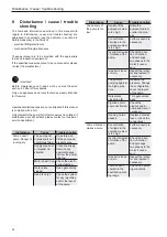
Disassembly / assembly
51
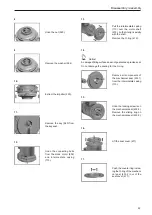
6.
Use assembly aids (acces-
sories) (if available) to ensure
an optimal seating of the
mechanical seal on the motor
shaft (819).
7.
Insert the key (940) into the
motor shaft groove.
8.
Slide the impeller (230) onto
the motor shaft (819).
9.
Slide the washer (554) onto
the motor shaft (819).
10.
Tighten the nut (920).
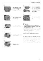
11.
Place the gasket (400.2)
between the pump casing
(101) and the intermediate
casing (113). Then insert the
complete interchangeable
module into the centering of
the pump casing.
12.
Screw the pump casing (101)
to the intermediate casing
(113).
Important!
- Check the free run of the impeller (230) by turning it!
- Establish the electrical connection of the block motor (see
section 5.4 Electrical connection)!
• Observe the connection type (refer to the name plate
on the motor)
• Observe the “clockwise” direction of rotation (see section
5.6 Direction of rotation check)
Start up the pump unit (see section 6 Commissioning).
9.2.2 Assembling the version with Seal-Guard-System
When inserting the pressure-sensitive counter ring ensure
- an even distribution of pressure,
- you use a clean pin with a soft seating and
- that no foreign particles are located on the sliding surfaces.
Summary of Contents for herborner.X
Page 4: ......


