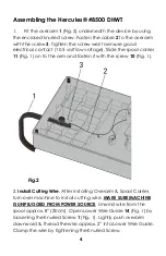
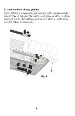
2
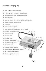
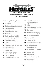
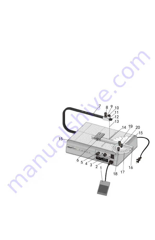
Overall view (Fig. 1):
1.
Foot Pedal control/ switch
2.
–
ON,
Օ
OFF,
=
FOOT PEDAL Mode
3. Temperature Level adjustment knob
4. Standby LED
5. Knurled screw for clamping the cutting wire
6. Circle cutting attachment
7. Overarm
8. Screw for wire spool
9. Wire spool
(Replacement wire #6555)
10.
Screw for spool carrier
11.
Spool carrier
12.
Guide slot
13.
Guide Wire
14.
Lower wire guide
15.
Slot for angle stop
16.
Extension rail
17.
Angle/ Miter gauge
18. Miter angle adjustment screw
19. Rail adjustment screw
20. Slide adjustment screw
Fig.1