background image

GETTING STARTED 

5

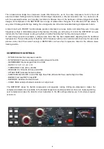
FRONT

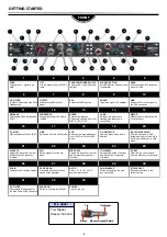
1

2

3

4

5

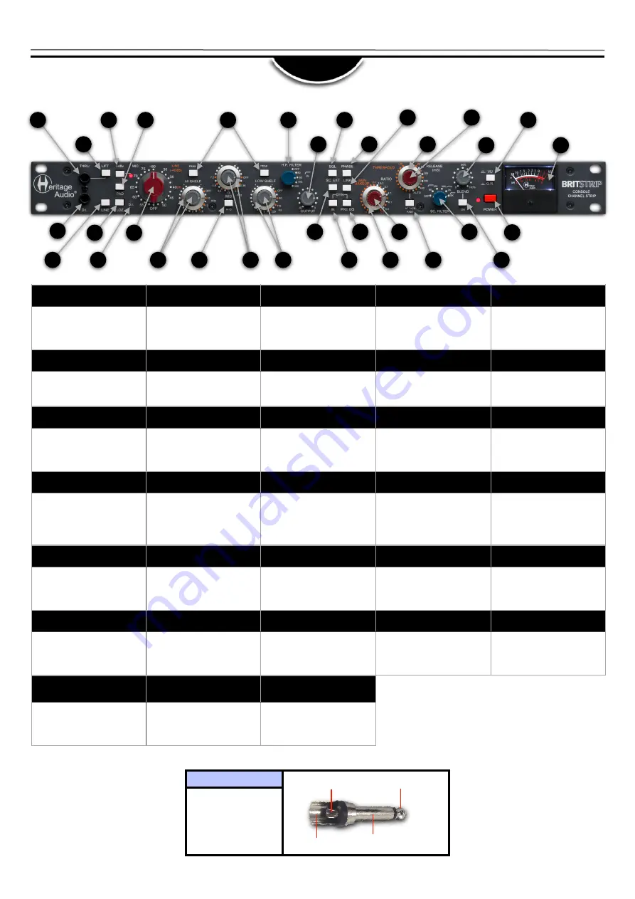
THRU

To send the D.I. signal to an 
AMP

LIFT

Lifts the ground from the THRU 
input

PHANTOM POWER SWITCH

Activates 48 V, with indicating 
red light

MIC PAD BUTTON

20 dB Reduction Ahead of Input 
Transformer

PEAK

Switches the SHELF response 
curve to PEAK

1

    D.I. Jack: 
  

Tip: Signal

Sleeve: Ground

Tip=Signal

Sleeve=Ground/Shield

Tip

Sleeve

2

3

4

6

7

8

9

5

10

11

12

13

14

15

16

17

18

19

20

21

22

23

24

25

27

29

28

26

30

31

32

33

6

7

8

9

10

H.P. FILTER

-3 dB at 4 Selectable High Pass 
Frequencies

OUTPUT

Attenuates the EQ output 
signal

EQL

Activates the EQ section

PHASE

Inverts the signal 180 degrees

LINK

Sends the DC control signal to 
the RCA connector

11

12

13

14

15

RELEASE

4 Selectable Fixed Options and 
AUTO

THRESHOLD

Fully variable from +20 dBu to 
-20 dBu

BLEND

Parallel Compression 
Continually variable from 100% 
WET to 100 % DRY

VU/GR

Switches the meter from 
tracking gain reduction to 
output level

METER

Measures Gain reduction in dB 
or Output level.

16

17

18

19

20

D.I. INPUT

High Impedance Class A JFET

LINE

Swaps the unit into LINE mode

LOZ 

Switches the input impedance 
from 1200 

Ω

 to 300

Ω

 in MIC 

mode

D.I. INDICATOR

Lights up green when jack is 
inserted

INPUT GAIN SWITCH

Sets the input gain in 5dB 
increments from 30 to 80 dB in 
MIC mode, 40 dB less in LINE 
mode

21

22

23

24

25

HI SHELF

Adjusts the Boost/Cut (Inside) 
and Selects the Frequency 
(Outside)

HI Q

Sets a higher Q for the mid 
band

MID SHELF

Adjusts the Boost/Cut (Inside) 
and Selects the Frequency 
(Outside)

LOW SHELF

Adjusts the Boost/Cut (Inside) 
and Selects the Frequency 
(Outside)

SC. EXT

Takes the AC control signal 
from the Sidechain In connector

26

27

28

29

30

DYN IN

Activates the Dynamics section

DYN PRE EQ

Places the dynamics section 
ahead of the equalizer

RATIO

From 1.5:1 to 10:1 on a 5 
position rotary switch

GAIN MAKEUP

Allows for restoring the gain 
loss up to 20dB

ATTACK FAST

Switches the attack to the 
fastest setting

31

32

33

SC. FILTER

4 Selectable Frequencies for 
the Side Chain of the Dynamics

BLEND ON

Switch to activate the BLEND

POWER

Turns on the unit

Summary of Contents for BRITSTRIP

Page 1: ...USER MANUAL August 2022 Rev 1 0 CHANNEL STRIP WITH DIODE BRIDGE COMPRESSOR RACKMOUNT...

Page 2: ...es them virtually unobtainable for the great majority Now it s possible to obtain that same sound with a brand new piece that will give you all the problem free heavy duty use you ll need for years of...

Page 3: ...former gives you lots of creative flexibility to push the signal as much as you see appropriate The D I also includes a passive thru output to feed a separate amplifier simultaneously while also passi...

Page 4: ...lter has been implemented departing from the traditional high pass one This provides plenty of flexibility with 5 frequency options and an external side chain input for even more precise control And i...

Page 5: ...TER Measures Gain reduction in dB or Output level 16 17 18 19 20 D I INPUT High Impedance Class A JFET LINE Swaps the unit into LINE mode LOZ Switches the input impedance from 1200 to 300 in MIC mode...

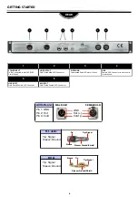
Page 6: ...CA Connector to pair to units for stereo use 6 3 2 1 D I Jack Tip Signal Sleeve Ground Tip Signal Sleeve Ground Shield Tip Sleeve All XLRs are Pin 1 GND Pin 2 Hot Pin 3 Cold 1 2 3 3 2 1 GND Hot Cold M...

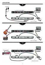
Page 7: ...UITAR FX PEDAL USB COMPUTER LINE OUTPUT KEYBOARD LINE INPUT ACTIVATE LINE SWITCH LINE INPUT AUDIO INTERFACE LINE INPUT AUDIO INTERFACE CONDENSER MIC OUTPUT ACTIVATE 48 V FOR CONDENSER MIC OUTPUT OUTPU...

Page 8: ...HI HAT TOM 1 OH L SNARE TOM 2 OH R 1 MIC INPUT 2 MIC INPUT 3 MIC INPUT 4 MIC INPUT 5 MIC INPUT 6 MIC INPUT 7 MIC INPUT 8 MIC INPUT 1 2 3 5 4 8 7 6 MONITOR SPEAKER THUNDERBOLT COMPUTER LINE INPUTS DRUM...

Page 9: ...PEAKERS ACTIVATE LINE SWITCH LINE OUTPUT CH 1 INTERFACE LINE INPUT CH 1 INTERFACE ACTIVATE LINE SWITCH 9 THUNDERBOLT COMPUTER MONITOR SPEAKERS TO EQ INPUT FROM EQ OUTPUT GRAPHIC EQ FOR SIDE CHAIN CONT...

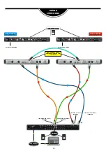
Page 10: ...ITCH LEFT CHANNEL ACTIVATE LINE SWITCH RIGHT CHANNEL ACTIVATE LINK SWITCH ACTIVATE LINK SWITCH LINE INPUT CH 1 LEFT INTERFACE LINE INPUT CH 2 RIGHT INTERFACE LINE OUTPUT CH 1 LEFT INTERFACE LINE OUTPU...

Page 11: ...0 THD Less than 0 025 at 1 kHz less than 0 05 at 100 Hz Frequency response 20 Hz 0 3 dB to 20 kHz 0 2 dB Maximum gain Slightly greater than 80 dB Noise Less than 125 dBu EIN 11 Maximum input level Ove...

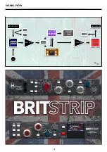
Page 12: ...SIGNAL FLOW 12 MIC LINE INPUT LINE OUTPUT PAD LOZ PHASE D I INPUT AMP OUTPUT AMP HIGH PASS FILTER EQUALIZER COMPRESSOR PRE EQ...

Page 13: ...ake sure the GAIN MAKEUP is not fully turned down There is a ground like noise on my amp Try pushing the LIFT button to see if it helps While adjusting the GAIN my signal suddenly disappears There is...

Page 14: ...date The warranty excludes problems due to normal wear abuse shipping damage or failure to use the product in accordance with the specifications Heritage Audio shall not be liable for damages based up...

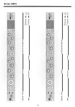
Page 15: ...RECALL SHEETS 15 Session Title Track Connected Equipment Date Instrument Notes Switch ON Switch OFF Session Title Track Connected Equipment Date Instrument Notes Switch ON Switch OFF...

Page 16: ...www heritageaudio com HERITAGE AUDIO C Alfonso G mez 38 3C 28037 Madrid Spain Tel 34 917 266 189 info heritageaudio com...

Reviews: