background image

GETTING STARTED 

4

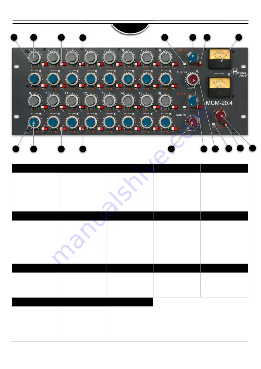
FRONT

1

2

3

4

5

6

7

8

9

10

11

12

13

14

15

16

17

18

1

2

3

4

5

PAN

Places  the  signal  within  the 
stereo  spectrum,  left,  center, 
right or any setting in between.

FADER

Attenuates  the  signal  sent  to 
the  Master  Bus  from  unity  to 
minus infinity. The control has a 
stepped  feel  for  easy  recall  of 
settings.


 All the way clockwise 

equals  unity  gain,  while  at  12 
o’clock  means  an  approximate 
20  dB  of  attenuation.  (Or  -20 
dB of gain).

ON (CHANNEL)

When pressed, the related input 
is added to the subgroup bus. 

INS (CHANNEL)

Turns  the  insert  on.  The  insert 
send  always  has  the  signal 
present, while pressing the INS 
switch  activates  the  insert 
return input.

ON (SUBGROUP)

When  pressed,  the  output  of 
the  subgroup  is  sent  to  the 
Master Bus. 

6

7

8

9

10

FADER

Attenuates  the  signal  sent  to 
the Subgroup bus from unity to 
minus  infinity.  All  the  way 
clockwise  equals  unity  gain, 
while  at  12  o’clock  means  an 
a p p r o x i m a t e  2 0  d B  o f 
attenuation. (Or -20 dB of gain).

INS (SUBGROUP)

Turns  the  insert  on.  The  insert 
send  always  has  the  signal 
present, while pressing the INS 
switch  activates  the  insert 
return input.

VU Meters

Measures  the  average  level  at 
the Master outputs. 
0 VU = +8 dBu.
Reads  post  fader  and  post 
insert.

AUX 2 / AUX

 3ST 

PAN 

Depending  on  the  status  of  the 
3ST button this outer ring either 
adjusts the amount sent to AUX 
2 or the Panning of Stereo AUX 
3. 

AUX 1 / AUX

 3ST 

SEND 

Depending  on  the  status  of  the 
3ST  button  this  either  adjusts 
the  amount  sent  to  AUX  1  or 
the Send of Stereo AUX 3. 


11

12

13

14

15

PRE

Changes the status of the AUX 
sends from POST to PRE. 

3ST

The 3ST button changes 
control from AUX 1&2 to AUX 
3.

AUX 3ST MASTER

Master volume send for Stereo 
AUX 3.

AUX 1 MASTER

Master volume send for Stereo 
AUX 1.

AUX 2 MASTER

Master volume send for Stereo 
AUX 2.

16

17

18

14

5

ON (MASTER)

When  pressed,  the  output  of 
the Master is sent to the Output 
connectors. 

INS (MASTER)

Turns  the  insert  on.  The  insert 
send  always  has  the  signal 
present, while pressing the INS 
switch  activates  the  insert 
return input.

MASTER FADER

Attenuates  the  Mix’s  output 
from unity to minus infinity. The 
control  has  a  stepped  feel  for 
easy  recall  of  settings.  All  the 
way  clockwise  equals  unity 
gain, while at 12 o’clock means 
an  approximate  20  dB  of 
attenuation. 

INPUT GAIN SWITCH

5dB Steps From 30 to 80

HI SHELF ± 15dB at 12 kHz

Summary of Contents for MCM-20.4

Page 1: ...USER MANUAL 20 CHANNEL SUMMING MIXER MCM 20 4 October 2022 Rev 1 0...

Page 2: ...asked for this equipment which makes them virtually unobtainable for the great majority Now it s possible to obtain that same sound with a brand new piece that will give you all the problem free heav...

Page 3: ...plus a balanced insert point and all stereo subgroups are passively summed into the master bus The gain is restored by means of a 73 style Class A transformer coupled mic preamplifier featuring a tota...

Page 4: ...e INS switch activates the insert return input VU Meters Measures the average level at the Master outputs 0 VU 8 dBu Reads post fader and post insert AUX 2 AUX 3ST PAN Depending on the status of the 3...

Page 5: ...TS 9 16 DB25 for Channel Input 9 16 INS RETURNS 9 16 DB25 for Insert Returns 9 16 INPUTS 1 32 DB25 4 for Channel Input 1 8 9 16 17 24 25 36 INS RETURNS 1 32 DB25 4 for Insert Returns 1 8 9 16 17 24 25...

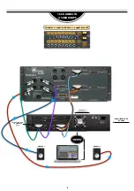
Page 6: ...6 8 CHANNEL SUMMING CHANNEL 1 8 SUBGROUP 1 2 MASTER APPLICATIONS MONITOR SPEAKERS THUNDERBOLT COMPUTER LINE OUTPUTS INPUT 1 8 INPUT 1 2 L R...

Page 7: ...THUNDERBOLT COMPUTER LINE OUTPUTS INPUT 1 8 FROM DAW INPUT 1 2 L R INPUT L R MASTER INPUT COMPRESSOR CHANNEL 1 8 INSERTS EQUALIZER INSERT SENDS 1 8 TO EQ MIX OUTPUT TO DAW L R INSERT RETURNS FROM EQ 1...

Page 8: ...4 SUBGROUPS THUNDERBOLT COMPUTER MONITOR L MONITOR R AUDIO INTERFACE I O 32x32 25 32 MIX OUTPUT L R TO CHANNELS 9 10 TRACKS 1 16 TO CHANNELS 1 16 25 32 17 24 9 16 1 8 CHANNEL 1 16 SUBGROUP 1 4 MASTER...

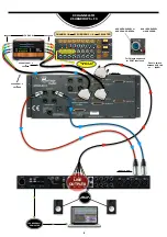
Page 9: ...INPUT 1 2 L R 8 CHANNELS TO 2 SUBGROUPS FX FX RACK INPUTS OUTPUTS AUX SENDS 1 2 3 STEREO CHANNELS 9 12 FX RETURNS AUX RETURNS 1 2 3 STEREO AUX 2 SEND LEVEL or AUX 3 PAN CONTROL AUX 1 SEND LEVEL or AUX...

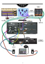
Page 10: ...LT COMPUTER LINE OUTPUTS INPUT 1 8 INPUT 1 2 L R 8 CHANNELS TO 4 SUBGROUPS INSERTS FX FX RACK INPUTS OUTPUTS AUX SENDS 1 2 3 STEREO CHANNELS 9 12 FX RETURNS AUX RETURNS 1 2 3 STEREO CHANNEL 1 4 INSERT...

Page 11: ...EL 1 16 SUBGROUP 1 4 MASTER 1 8 9 16 17 24 CHANNEL 1 16 PREAMPS GROUP INSTRUMENTS SIGNALS 1 16 MIX OUTPUT L R TO CHANNELS 17 18 25 32 17 24 9 16 1 8 CHANNEL 1 16 PREAMP OUTPUTS PREAMP OUTPUTS TO DAW I...

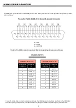
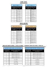
Page 12: ...NNEL CHANNEL I P 1 8 1 INPUT 1 2 INPUT 2 3 INPUT 3 4 INPUT 4 5 INPUT 5 6 INPUT 6 7 INPUT 7 8 INPUT 8 It is worth noting that in order to avoid ground loops the DB25 ground connections are lifted on th...

Page 13: ...2 3 INS RETURN 3 4 INS RETURN 4 5 INS RETURN 5 6 INS RETURN 6 7 INS RETURN 7 8 INS RETURN 8 TASCAM DSUB CHANNEL INS RETURNS 1 8 INSERT RETURNS 1 8 INSERT RETURNS 1 SUBGROUP INSERT SEND 1 2 SUBGROUP IN...

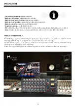
Page 14: ...to 600 Noise All faders up all subgroups in measured at the main output 22 Hz to 22 kHz Better than 80 dBu 14 MCM 20 4 POWER SUPPLY The MCM range of summing mixers features a hybrid power supply conce...

Page 15: ...W INPUTS INSERTS TLA AMP ON FADER PAN SUBGROUP O P 1 SUBGROUP O P 2 1 2 3 4 5 6 7 8 CHANNEL 1 8 SECTION INPUTS INSERTS TLA AMP ON FADER PAN SUBGROUP O P 3 SUBGROUP O P 4 1 2 3 4 5 6 7 8 CHANNEL 9 16 S...

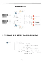
Page 16: ...CTION DETAILED AUX SEND SECTION SAME ALL CHANNELS SUBGROUP O P 1 SUBGROUP O P 3 AUX INPUT 1 AUX INPUT 3 SUBGROUP O P 2 SUBGROUP O P 4 AUX INPUT 2 AUX INPUT 4 MASTER OUT L MASTER OUT R MONITOR OUT L MO...

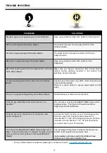
Page 17: ...to both sides There is no signal at all appearing at the Stereo Master Double check your cables and connections I d like to get a Direct Out from each channel Is it possible Yes of course Just tap the...

Page 18: ...chase date The warranty excludes problems due to normal wear abuse shipping damage or failure to use the product in accordance with the specifications Heritage Audio shall not be liable for damages ba...

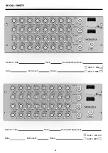
Page 19: ...3ST SEND 3ST SEND 3ST SEND 3ST SEND 3ST SEND 3ST SEND 3ST SEND 3ST SEND 3ST SEND 3ST SEND 3ST SEND 3ST SEND Session Title Track Connected Equipment Date Instrument Notes Switch ON Switch OFF SUB 1 2...

Page 20: ...www heritageaudio com HERITAGE AUDIO C Alfonso G mez 38 3C 28037 Madrid Spain Tel 34 917 266 189 info heritageaudio com...

Reviews: