background image

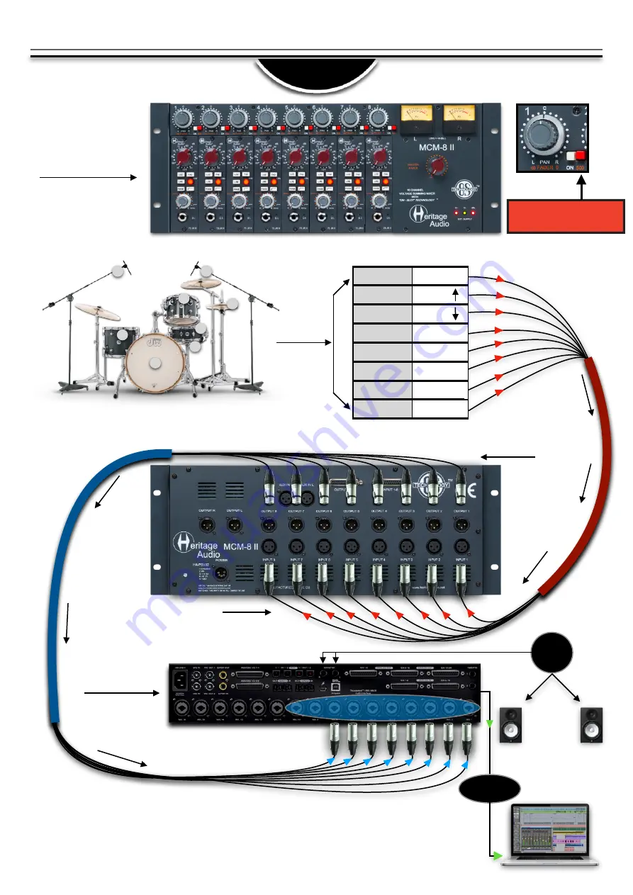
RECORDING

APPLICATIONS 

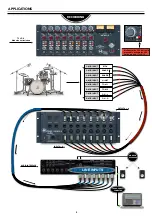
MONITOR 

SPEAKERS 

THUNDERBOLT 

 COMPUTER 

KICK

SNARE

HI HAT 

TOM 1

OH - L

SNARE

TOM 2

OH - R

1 - MIC INPUT

2 - MIC INPUT

3 - MIC INPUT

4 - MIC INPUT

5 - MIC INPUT

6 - MIC INPUT

7 - MIC INPUT

8 - MIC INPUT

OUTPUTS 1-8

1

2

3

5

4

8

6

7

INPUTS 1-8

LINE INPUTS

AUDIO INTERFACE

5

73 JR II 

 Modules not included

Make sure the ´500´ button is 
pressed to activate the 500 
Series module. (73 JR II)

Summary of Contents for MCM-8 II

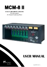
Page 1: ...USER MANUAL 8 SLOT 500 SERIES CHASSIS With Integrated 10 Channel Summing Mixer MCM 8 II August 2022 Rev 1 0...

Page 2: ...es them virtually unobtainable for the great majority Now it s possible to obtain that same sound with a brand new piece that will give you all the problem free heavy duty use you ll need for years of...

Page 3: ...tal enclosure With literally hundreds of brands making 500 series modules we at Heritage Audio think this is the professional way of handling this reliably eliminating issues often associated with sha...

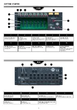
Page 4: ...S L R On Gold Plated XLRs OUTPUTS 1 8 25 PIN D SUB DB25 CONNECTOR INPUTS 1 8 25 PIN D SUB DB25 CONNECTOR 6 7 8 9 10 CHANNEL ON OFF On sends Signal to Stereo summing bus 500 BUTTON Routes the Signal Th...

Page 5: ...SNARE TOM 2 OH R 1 MIC INPUT 2 MIC INPUT 3 MIC INPUT 4 MIC INPUT 5 MIC INPUT 6 MIC INPUT 7 MIC INPUT 8 MIC INPUT OUTPUTS 1 8 1 2 3 5 4 8 6 7 INPUTS 1 8 LINE INPUTS AUDIO INTERFACE 5 73 JR II Modules n...

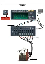
Page 6: ...6 SUMMING USB COMPUTER LINE INPUTS AUDIO INTERFACE SUMMED OUTPUTS L R MCM 8 II INPUTS 1 8 MULTITRACK OUTPUTS 1 8 Make sure the On button is pressed to send the signal on to the Stereo Bus for summing...

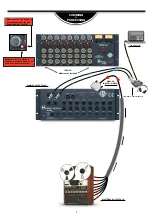
Page 7: ...SUMMED OUTPUTS L R MULTITRACK OUTPUTS 1 8 Make sure the On button is pressed to send the signal on to the Stereo Bus for summing MCM 8 II INPUTS 1 8 DB25 Make sure the 500 button is pressed to activat...

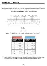
Page 8: ...ANNEL CHANNEL I P 1 8 1 OUTPUT 1 2 OUTPUT 2 3 OUTPUT 3 4 OUTPUT 4 5 OUTPUT 5 6 OUTPUT 6 7 OUTPUT 7 8 OUTPUT 8 It is worth noting that in order to avoid ground loops the DB25 ground connections are lif...

Page 9: ...100 240 V AC Dimensions W x H x L 482 mm x 220 mm 5 Rack units x 185 mm 9 Modules 73 EQ JR not included ENCLOSURE SECTION Channel Input Impedance 20 k Maximum input level Over 27 dBu Maximum output le...

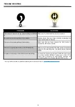
Page 10: ...tton to activate the 500 Series module There is no signal present at the L R XLR Outputs Make sure you have pressed the ON button to send the signal to the summing bus the MAIN Stereo Outputs L R 8 in...

Page 11: ...warranty excludes problems due to normal wear abuse shipping damage or failure to use the product in accordance with the specifications Heritage Audio shall not be liable for damages based upon inconv...

Page 12: ...RECALL SHEETS 12 Session Title Track Connected Equipment Date Instrument Notes Switch ON Switch OFF Session Title Track Connected Equipment Date Instrument Notes Switch ON Switch OFF...

Page 13: ...www heritageaudio com HERITAGE AUDIO C Alfonso G mez 38 3C 28037 Madrid Spain Tel 34 917 266 189 info heritageaudio com...

Reviews: