21
Installation
for the technician
Flue systems
HABITAT 2 SE
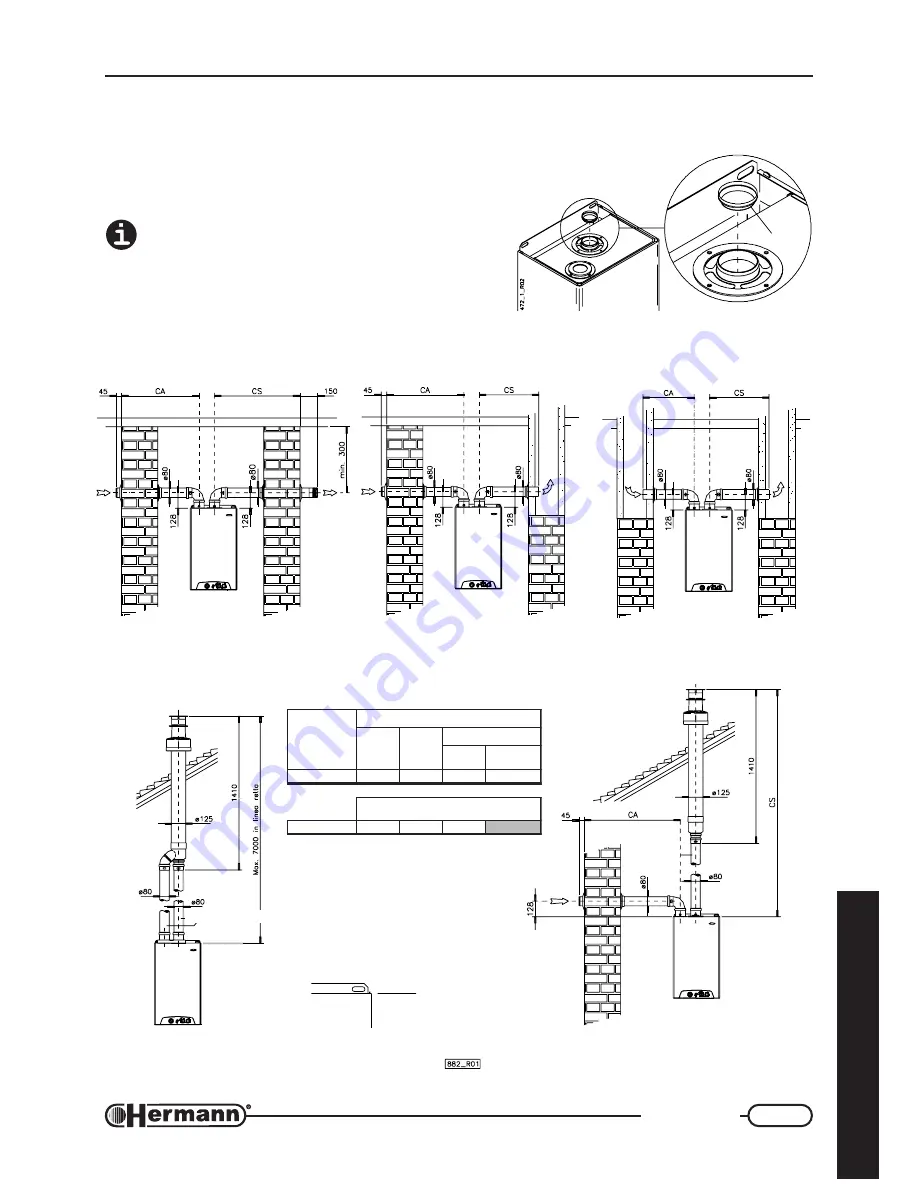
AIR INLET AND PRODUCTS OUTLET THROUGH
SEPARATE PIPES
Attention: see table and, if required, install the
diaphragm
“D”
as indicated in the figure besides
(any additional 90° bend = 0.5 linear meters, 45°
bend = 0.25 meters).
FLUE
AIR INLET
DUCT
FLUE
AIR INLET THROUGH DUCT
PRODUCTS OUTLET TO FLUE
AIR INLET THROUGH WALL
PRODUCTS OUTLET TO FLUE
AIR INLET AND PRODUCTS OUTLET
THROUGH WALL
Measures are relevant
to upper edge
of boiler’s body
SEPARATE PIPES WITH PIPES-SPLIT
VERTICAL OUTLET/INLET
SEPARATE PIPES
VERTICAL OUTLET
Extension on request
Extension
on request
D
l
e
d
o
M
s
t
c
u
d
d
e
t
a
r
a
p
e
s
m
m
0
8
Ø
S
C
+
A
C
x
a
m
÷
n
i
m
)
m
(
S
C
x
a
m
)
m
(
m
g
a
r
h
p
a
i
D
r
e
t
e
m
a
i
d
)
m
m
(
o
t
p
u
)
m
(
S
C
+
A
C
E
S
4
2
0
3
÷
2
0
2
)
a
(
8
s
t
c
u
d
m
m
0
8
Ø
n
o
it
c
e
n
n
o
c
l
a
i
x
a
o
c
n
o
r
e
tt
il
p
S
s
e
p
i
P
h
ti
w
E
S
4
2
4
1
÷
2
3
1
O
N
(a) use the diaphragm supplied with the boiler.


