background image

............................................................................................3

.........................................................................................................6

......................................................................................7

..............................................................9

.....................................................................10

...............................................................................................................12

........................................................................................................17

.......................................................................................18

.................................................................28

..............................................................29

.......................................................................................27

2

Summary of Contents for HT-07

Page 1: ......

Page 2: ......

Page 3: ... 3 6 7 9 10 12 17 18 28 29 27 2 ...

Page 4: ...3 ...

Page 5: ...4 ...

Page 6: ...5 ...

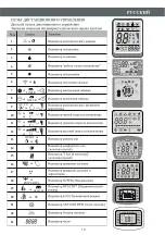
Page 7: ...1 2 3 4 5 6 7 8 9 10 13 14 15 16 11 17 12 13 15 16 17 6 1 2 3 6 4 5 9 11 8 10 7 14 DIS PLA Y HEA LTH Y 3D ON O FF SW ING FA N TIM ER SU PE R SL EE P MO DE EC O CLO CK 12 No No ...

Page 8: ...7 No 1 2 3 4 5 1 2 5 3 4 1 2 3 4 5 1 2 4 5 3 1 2 3 4 5 3 1 2 3 5 4 3 4 2 1 2 4 5 ...

Page 9: ...ON OFF ON OFF POWER SLEEP TIMER RUN 8 Àâàðèéíàÿ ê ê íîï à Àâàðèéíàÿ ê ê íîï à Àâàðèéíàÿ ê ê íîï à äèñïë é å ON OFF ...

Page 10: ...9 13 8 12 4 14 10 5 6 DISPLAY HEALTHY 3D CLOCK 7 1 3 4 5 12 13 10 9 8 7 6 ON OFF ON C AUTOQUIET POWERFUL hr DELAY DRY FAN HEAT TIMER HEALTHY AIR SWING FAN SPEED 2 COOL FEEL ON OFF MODE TIMER FAN SPEED SUPER ECO ANTI MILDEW SWING SLEEP HEALTHY DISPLAY RESET 15 16 ON MODE FAN SLEEP ECO TIMER SWING TURBO HEALTHY DISPLAY SWING 6 8 1 2 3 5 12 13 10 10 4 7 9 6 5 8 2 1 3 4 MID AUTO SWING X HIGH LOW DRY F...

Page 11: ...or 20 21 22 FLASH 23 No Auto Feel Cool Dry Heat Low Mid High Sleep Swing Timer OFF Timer Fan ON OFF ON C AUTOQUIET POWERFUL hr DELAY DRY FAN HEAT TIMER HEALTHY AIR SWING FAN SPEED COOL FEEL C h C h MID AUTO SLEEP TIMER ON HIGH LOW TMIER OFF DRY FAN HEAT COOL FEEL SWING TIMER HEALTHY ON MID AUTO SWING X HIGH LOW DRY FAN COOL FEEL SWING Y SUPER HEAT SLEEP TIMER ON TIMER OFF ...

Page 12: ...ING FAN SPEED COOL FEEL ii DISPL AY HEAL THY 3D ON OFF SWI NG FAN TIME R SUP ER SLE EP MOD E ECO CLOC K DIS PLA Y HEA LTH Y 3D ON OFF SW ING FA N TIM ER SU PE R SL EE P MO DE EC O CLO CK DIS PLA Y HEA LTH Y 3D ON OFF SW ING FA N TIM ER SU PE R SL EE P MO DE EC O CLO CK C F Ïðèåìíèê í àëà ñ ãí i ...

Page 13: ...ING ON OFF MODE TIMER FAN SPEED SUPER ECO SWING SLEEP HEALTHY ANTI MILDEW MODE FAN SLEEP ECO TIMER SWING TURBO HEALTHY DISPLAY SWING AIR SWING OFF ON C AUTOQUIET POWERFUL hr DELAY TIMER HEALTHY AIR SWING FAN SPEED DRY FAN HEAT COOL FEEL C h ON TIMER HEALTHY SWING ...

Page 14: ...EED SUPER ECO SWING SLEEP HEALTHY DRY FAN HEAT COOL FEEL ANTI MILDEW C h ON COOL 1 2 3 OFF C AUTOQUIET POWERFUL TIMER HEALTHY DRY FAN HEAT COOL FEEL ON HEAT ON hr DELAY AIR SWING FAN SPEED C h 1 ON OFF MODE TIMER FAN SPEED SUPER ECO SWING SLEEP HEALTHY ANTI MILDEW 1 2 3 1 TIMER HEALTHY TIMER HEALTHY COOL HEAT ...

Page 15: ...HY DRY FAN HEAT COOL FEEL ANTI MILDEW C h ON 1 2 3 TIMER HEALTHY TIMER HEALTHY TIMER HEALTHY POWER SLEEP TIMER RUN TIMER OFF ON C AUTOQUIET POWERFUL hr DELAY TIMER HEALTHY AIR SWING FAN SPEED DRY FAN HEAT COOL FEEL C h ON OFF ON OFF MODE TIMER FAN SPEED SUPER ECO SWING SLEEP HEALTHY ANTI MILDEW 1 ýê í ðåííåã ë ðàí â óò î á îêà ýê í ðåííåã ë ðàí â óò î á îêà ýê í ðåííåã ë ðàí â óò î á îêà TIMER TIM...

Page 16: ...R FAN SPEED SUPER ECO SWING SLEEP HEALTHY DRY FAN HEAT COOL FEEL ANTI MILDEW C h ON 3 FAN DRY OFF ON C AUTOQUIET POWERFUL hr DELAY TIMER HEALTHY AIR SWING FAN SPEED ON OFF MODE TIMER FAN SPEED SUPER ECO SWING SLEEP HEALTHY DRY FAN HEAT COOL FEEL ANTI MILDEW C h ON TIMER HEALTHY TIMER HEALTHY FAN DRY ...

Page 17: ...ON ON OFF MODE TIMER FAN SPEED SUPER ECO SWING SLEEP HEALTHY ANTI MILDEW 1 2 3 OFF ON C AUTOQUIET POWERFUL hr DELAY TIMER HEALTHY AIR SWING FAN SPEED DRY FAN HEAT COOL FEEL C h ON ON OFF MODE TIMER FAN SPEED SUPER ECO SWING SLEEP HEALTHY ANTI MILDEW AUTOQUIET 1 TIMER HEALTHY TIMER HEALTHY Àâòîìàòè åñêèé ðåæèì Îñóøåíèå Îõëàæäåíèå ýê í ðåííåã ë ðàí â óò î á îêà SLEEP ...

Page 18: ...2 1 3 17 2 1 3 NO NO Íàãðåâàíèå Îõëàæäåíèå Îñóøåíèå Íàãðåâàíèå Îõëàæäåíèå Îñóøåíèå ...

Page 19: ...çàíî â ðèñóíêå Íàðóæíûé áëîê Äëèíà òðóáà 15ì ìàêñèìàëüíî Âíóòðåííèé áëîê Âûñî òà äîëæ íà íèæå 5ì Âíóòðåííèé áëîê Äëèíà òðóáà 15ì ìàêñèìàëüíî Íàðóæíûé áëîê Âûñîòà äîëæíà íèæå 5ì èçîëÿöèÿ ýëåêòðè åñêèé êàáåëü òðóáû ñ î û ëèâà â ä óñò àíîâî íàÿ ïëèòà â ëêà òó òðóáà ëèâà êîíäåí à à ñ ñ ò ...

Page 20: ...50 5mm 18 Â ïîìåùåíèè Íàîòðûòîì âîçäóõå Ïåðåäíÿÿ ïàíåëü ñõåìà ñîåäèíåíèé Êðûøêà êëåììíèêà êîëîäêè ...

Page 21: ...3 2 1 YES 20 NO NO NO YES Ôîðìèðîâàòü ñîåäèíÿþùèé ïðîâîä Ïðîäëèòü çàâåðíóòûé ïðîâîä Ìîìåíòíûé êëþ ...

Page 22: ...èðóþùèé ñòàêàí Ïðîâîä õëàäàãåíòà Ñîåäèíèòåëüíûé êàáåëü Ñîåäèòèíèòåëüíûé êàáåëü 1 äëÿ íàãðåâàþùåãî íàñîñà Çîíäêàáåëü äëÿ íàãðåâàþùåãî íàñîñà Îòâîäíàÿ òðóáêà êîíäåíñàöèîííîé âîäû Ïðîâîä õëàäàãåíòà Äðåíàæíûé êàíàë îòâîäíàÿ òðóáêà ìîíòàæíàÿ ïëèòà ...

Page 23: ...íà ñïèíå êðûøêè Ïðèâèí èâàòü Ñíèìàòü âåðõíþþ êðûøêó Íàðóæíûé áëîê Ñîåäèíèòåëüíûå òðóáû Êîíóñíûå ãàéêè Âåíòèëü æèäêîñòè Âåíòèëü ãàçà Âíóòðåííèé áëîê Ãàçîâûé âåíòèëü Æèäêîñòíîé âåíòèëü Ãàéêà ñåðâèñíîãî ïîðòà Çàùèòíàÿ êðûøêà Ñåðâèñíûé ïîðò Âàêêóì íàñîñ ...

Page 24: ...õëàäàãåíòà åòûðåõ õîäîâîé êëàïàí 7 Ïîâîðà èâàòü êëàïàí äî ïîëíîãî îòêðûòèÿ 1 Ïîâîðà èâàòü 8 Óðåïèòü Êðûøêà âåíòèëÿ 8 Óðåïèòü 2 Ïîâîðà èâàòü Ãàéêà ñåðâèñíîãî ïîðòà òðåõ õîäîâîé êëàïàí 6 Îòêðûâàòü íà 1 4 êðóãà 7 Ïîâîðà èâàòü êëàïàí äî ïîëíîãî îòêðûòèÿ Êðûøêà âåíòèëÿ 1 Ïîâîðà èâàòü 8 Óðåïèòü çàäåæêè Èçîëÿöèîííàÿ êðûøêà Òðóáîïðîâîä Òðóáîïðîâîä Èçîëåíòà Âíóòðåííèé Íàðóæíûì Ïðîêëàäêà ñ åíà ò ...

Page 25: ...g m 20g m 30g m 30g m 30g m 5m 5m 5m 5m 5m 5m R410A R410A R410A R410A R410A R410A 9k 12k 15 18k 22 24k 1 4 6 1 4 6 1 4 6 3 8 9 52 1 2 12 3 8 9 52 5 8 15 88 3m 3m 4m 4m 15m 15m 15m 15m 20g m 20g m 30g m 30g m 5m 5m 5m 5m R410A 1 4 6 3 8 9 52 1 2 12 5 8 15 88 15 20 31 35 35 45 75 80 7 9 25 30 3 8 9 52 28 30 36k R410A R410A R410A R410A 1 2 12 3m 15m 20g m 5m 3 8 9 52 ...

Page 26: ...25 ...

Page 27: ... 2 2 5mm 2 1 5mm 2 1 0mm 2 1 5mm 2 1 0mm 2 1 5mm 2 1 0mm 2 1 5mm 2 1 0mm 2 1 5mm 2 1 5mm 2 1 5mm 2 1 5mm 2 1 0mm 2 1 5mm 2 1 0mm 2 1 5mm 2 1 0mm 2 0 75mm 2 1 5mm 2 1 0mm 2 1 5mm 2 1 0mm 2 1 5mm 2 1 5mm 2 1 0mm AWG16 AWG18 AWG16 AWG18 AWG16 2 1 5mm 2 2 5mm 2 1 5mm 2 1 0mm 2 1 5mm 2 1 0mm AWG16 AWG18 AWG16 AWG18 AWG16 2 1 5mm 2 2 5mm 2 1 5mm 2 1 0mm 2 1 5mm 2 1 0mm AWG16 AWG18 AWG16 AWG18 AWG16 AWG1...

Page 28: ...27 Ô ð ð èëüò ï îòèâ ïûëè ...

Page 29: ...28 ...

Page 30: ......

Page 31: ...S OF PARTS INDOOR UNIT DISPLAY OPERATING INSTRUCTIONS PROTECTION INSTALLATION MANUAL MAINTENANCE TROUBLESHOOTING EMERGENCY FUNCTION AUTO RESTART FUNCTION REMOTE CONTROLLER 31 34 35 36 37 40 45 46 55 56 ENVIRONMENT FRIENDLY DISPOSAL 57 ...

Page 32: ...ackaging materials are recyclable and should be disposed of in the separate waste bins Take the air conditioner at the end of its useful life to a special waste collection centre for disposal Only use the air conditioner as instructed in this booklet These instructions are not inten ded to cover every possible condition and situation As with any electrical household appliance common sense and caut...

Page 33: ...or any other purpose such as for drying clothes cooling food etc The packaging materials are recyclable and should be disposed of in the sparate waste bins Take the air conditioner at the end of its useful life to a special waste collection centre for disposal Only use the air conditioner as instructed in this booklet These instructions are not int end ed to cover every possible condition and situ...

Page 34: ... Do not leave windows or doors open for long when the air conditioner is operating Do not direct the airflow onto plants or anim als A long direct exposition to the flow of cold air of the conditioner could have negative effects on plants and animals Do not put the conditioner in contact with water The electrical insulation could be damaged and thus causing electrocution Do not climb onto or place...

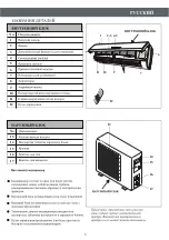
Page 35: ...ram of the appliance and may not correspond to the appearance of the units that have been purchased No Description 13 Air outlet grille Terminal block cover 14 gas valve 15 liquid valve 16 11 Indoor unit rating label Stick position optional 17 Outdoor unit rating label 12 Ionizer if installed generator 13 15 16 17 INDOOR UNIT 34 OUTDOOR UNIT 1 2 3 6 4 5 9 11 8 10 7 14 DIS PLA Y HEA LTH Y 3D ON O F...

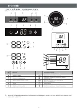
Page 36: ...ed Function POWER This symbol appears when the unit is power on 1 2 3 4 5 Temperature display if present Error code 1 Lights up during Timer operation when the air conditioner is operational 2 Displays the malfunction code when fault occurs SLEEP mode Lights up during Timer operation The symbol appears when the unit is turned on and disappear when the unit is turned off SLEEP TIMER RUN 3 4 2 1 2 4...

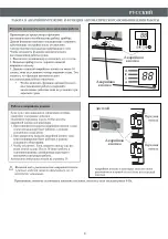
Page 37: ...wo press of the emergency button within 3 sec two beeps will lead to the forced HEATING operation 3 To switch off the unit you just need to press the button again a single long beep 4 After 30 minutes in forced operation the air conditioner will automatically start working in 23 cooling mode auto fan speed The FEEL function is described in page 13 If the remote controller fails to work or maintena...

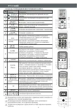
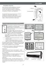
Page 38: ...tton which controls the ionizer or plasma generator only for inverter models In cooling mode press this button the temperature will increase 2 on the base of setting temperature In heating mode press this button the temperature will decrease 2 on the base of setting temperature Press this button to activate deactivate the Super function which enables the unit to reach the preset temperature in the...

Page 39: ... indicator SIGNAL RECEPTION indicator TIMER OFF indicator TIMER ON indicator AUTO FAN indicator LOW FAN SPEED indicator or MIDDLE FAN SPEED indicator or or HIGH FAN SPEED indicator QUIET or or SLEEP indicator or AUTO or or FLAP SWING indicator 15 SUPER indicator 16 17 HEALTHY indicator TIMER ON or or TIMER OFF or HEALTHY ON 18 ECO indicator 19 ANTI MILDEW indicator or POWERFUL or or EC or BATTERY ...

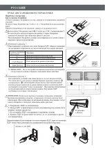
Page 40: ...oward the Air conditioner 2 Check that there are no objects between the remote control and the Signal receptor in the indoor unit 3 Never leave the remote controller exposed to the rays of the sun 4 Keep the remote controller at a distance of at least 1m from the television or other electrical appliances Recommendations for locating and using the remote controller holder if present The remote cont...

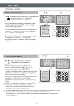
Page 41: ...t ributed in the room It is possible to position the direction of the air in the optimal In cooling mode orient the flaps in horizontal direction In heating mode orient the flaps downward as the warm air tends to rise The deflectors are positioned manually and placed un der the flaps They allow to direct the air flow rightw ard or leftward Never position Flaps manually the delicate mech anism migh...

Page 42: ...tioner adjust the temperature 1 the speed 2 and the direction of the air flow 3 by pressing the button indicated HEAT The heating function allows the air conditi oner to heat the room To activate the heating function HEAT press the MODE button until the symbol HEAT appears on the display With the button or set a temperature higher than that of the room To optimize the function of theAir conditione...

Page 43: ...ld be power off Press TIMER at the fist time set the temperature with pressing the button or Press TIMER at the second time set the rest time with pressing the button or Press TIMER at the third time confirm the setting then the rest time to next automatical switching on could be read on the display NOTE Before proceeding with the time program the working mode with the button MODE 2 and the fan sp...

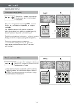
Page 44: ...ING or HEATING This function reduces the humid ity of the air to make the room more comfortable To set the DRY mode Press MODE untill DRY appears in the display An automatic function of alternating cooling cycles and air fan is activated DRY FAN MODE DRY MODE OFF ON C AUTOQUIET POWERFUL hr DELAY TIMER HEALTHY AIR SWING FAN SPEED ON OFF MODE TIMER FAN SPEED SUPER ECO SWING SLEEP HEALTHY DRY FAN HEA...

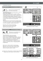
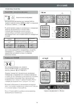
Page 45: ...is gradually decreased by 2 during the first 2 hours of operation After 10 hours running in sleep mode the air conditio ner is swicthed off automatically 44 I FEEL MODE POWER SLEEP TIMER RUN Indoor display FEEL OFF ON C AUTOQUIET POWERFUL hr DELAY TIMER HEALTHY AIR SWING FAN SPEED DRY FAN HEAT COOL FEEL C h ON ON OFF MODE TIMER FAN SPEED SUPER ECO SWING SLEEP HEALTHY ANTI MILDEW 1 2 3 OFF ON C AUT...

Page 46: ...low 21 Room temperature is below 18 C For T1 Climate condition models For Tropical T3 Climate condition models The unit does not operate immediately if it is turned on after being turned off or after changing the mode during operation this is a normal self protection action you need wait for about 3 minutes No MODE 2 1 3 Heating Cooling Dry No MODE Outdoor temperature is over 24 Room temperature i...

Page 47: ...ed mm showing in the picture 50 0 Outdoor unit Indoor unit be less than 5m Height should Outdoor unit Indoor unit be less than 5m Height should Installation Diagram 46 INDOOR UNIT OUTDOOR UNIT The purchaser must ensure that the person and or company who is to install maintain or repair this air conditioner has qualifications and experience in refrigerant products Install the indoor unit on a stron...

Page 48: ...pping screws 5 Be sure that the rear panel has been fixed firmly enough to withstand the weight 1 Make the piping hole 55 in the wall at a slight downward slant to the outdoor side 2 Insert the piping hole sleeve into the hole to prevent the connection piping and wiring from being damaged when passing through the hole 1 Open the front panel 2 Take off the cover as indicated in the piciure by remov...

Page 49: ...lace the drain hose below the piping taking care not to create siphons 2 The drain hose must slant downwards to aid drainage 3 Do not bend the drain hose or leave it protruding or twisted and do not put the end of it in water If an extension is connected to the drain hose ensure that it is lagged when it passes into the indoor unit 4 If the piping is installed to the right the pipes power cable an...

Page 50: ... unit The outdoor unit should be installed on a solid wall and fastened securely The following procedure must be observed before co nnecting the pipes and connecting cables decide which is the best position on the wall and leave enough space to be able to carry out maintenance easily Fasten the support to the wall using screw anchors which are particularly suited to the type of wall Use a larger q...

Page 51: ...kage as the flange could be damaged 3 The surest system consists in tightening the connecti on by using a fix wrench and a torque wrench in this case use the table on page 22 vacuum pump service port Air and humidity left inside the refrigerant circuit can cause compressor malfunction After having connected the indoor and outdoor units bleed the air and humidity from the refrigerant circuit by usi...

Page 52: ...vacuum pump hose 8 Replace and tighten all the caps on the valves 3 way valve diagram connect to indoor unit open position spindle service port cap Connect to outdoor unit Valve core needle INSTALLATION MANUAL operation test wall indoor outdoor piping piping gasket insulating tape insulating covering Clamps 1 Wind insulating covering around the joints of the ind oor unit and fix it with insulating...

Page 53: ...g m 20g m 30g m 30g m 30g m 5m 5m 5m 5m 5m 5m 5m R22 MODEL capacity Btu h 7k 9k 12k 15 18k 22 24k 28 30k 36k Liquid pipe diameter Gas pipe diameter Lenght of pipe with standard charge Maximum distance between indoor and outdoor unit Max diff in level between indoor and outdoor unit Type of refrigerant 1 1 4 6 1 4 6 1 4 6 1 4 6 3 8 9 52 3 8 9 52 1 2 12 3 8 9 52 3 8 9 52 5 8 15 88 5 8 15 88 3m 3m 3m...

Page 54: ...minal block For different models the wiring diagram may be different Please refer to the wiring diagrams pasted on the indoor unit and outdoor unit respectively On indoor unit the wiring diagram is pasted under the front panel On outdoor unit the wiring diagram is pasted on the backside of the outdoor handle cover Front panel Wiring diagram Wiring diagram Outdoor handle cover ...

Page 55: ... 5mm 2 1 0mm 2 1 5mm 2 1 5mm 2 1 5mm 2 1 5mm 2 1 0mm 2 1 5mm 2 1 0mm 2 1 5mm 2 1 0mm 2 0 75mm 2 1 5mm 2 1 0mm 2 1 5mm 2 1 0mm 2 1 5mm 2 1 5mm 2 1 0mm INVERTER TYPE MODEL capacity Btu h AWG16 AWG18 AWG16 AWG18 AWG16 2 1 5mm 2 2 5mm 2 1 5mm 2 1 0mm 2 1 5mm 2 1 0mm AWG16 AWG18 AWG16 AWG18 AWG16 2 1 5mm 2 2 5mm 2 1 5mm 2 1 0mm 2 1 5mm 2 1 0mm AWG16 AWG18 AWG16 AWG18 AWG16 AWG18 AWG16 AWG18 AWG18 AWG18...

Page 56: ...life it till its greatest stroke and then unhooking it from the hinges to make the cleaning easier 2 Clean the indoor unit using a cloth with the water not higher than 40 and neutral soap Never use aggressive solvents or detergents 3 If the outdoor unit is clogged remove the leaves and the waste and remove the dust with air jet or a bit of water END OF SEASON MAINTENANCE 1 Disconnect the automatic...

Page 57: ... This occurs when the air in the room becomes very cold for example in the COOLING or DEHUMIDIFYING DRY modes This noise is made by the expansion or contraction of the front panel due to variations in temperature and does not indicate a problem Inappropriate temperature setting Air inlet or outlet of indoor or outdoor unit has been blocked Air filter is blocked Fan speed set at minimum Other sourc...

Page 58: ...NVIRONMENT FRIENDLY DISPOSAL You can help protect the environment Please remember to respect the local regulations hand in the non working electrical equipments to an appropriate waste disposal center 57 ...

Page 59: ......

Page 60: ......

Page 61: ......

Page 62: ... ...

Page 63: ......

Page 64: ......

Reviews: