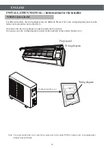
INSTALLATION MANUAL---Installation of the outdoor unit
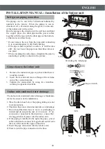
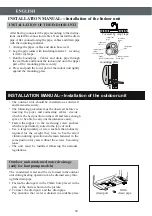
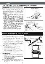
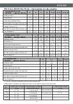
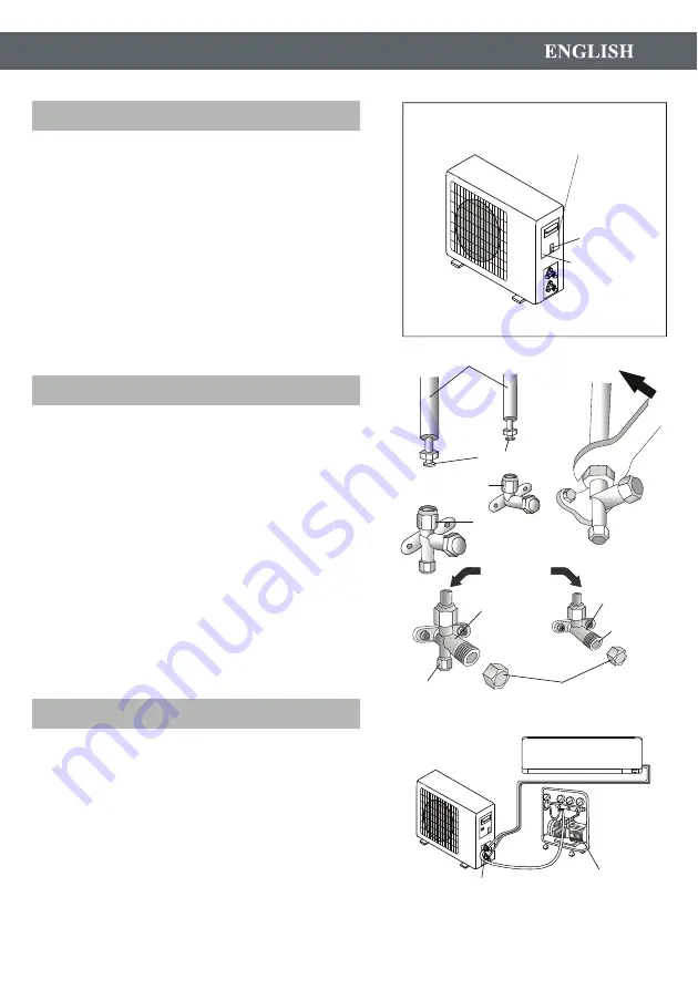
outdoor unit
screw
wiring diagram on the
back of the cover
Screw the flare nuts to the outdoor unit coupling with
the same tightening procedures described for the indoor
unit.
connection pipes
flare nuts
liquid tap
gas tap
indoor unit
protection caps
liquid valve
gas valve
service port nut
To avoid leakage, pay attention to the following points:
1. Tighten the flare nuts using two wrenches. Pay atten-
tion not to damage the pipes.
2. If the tightening torque is not sufficient , there will
probably be some leakage. With excessive tightening
torque there will also be some leakage, as the flange
could be damaged.
3. The surest system consists in tightening the connecti-
on by using a fix wrench and a torque wrench:in this
case use the table on page 22.
vacuum pump
service port
Air and humidity left inside the refrigerant circuit can
cause compressor malfunction. After having connected
the indoor and outdoor units, bleed the air and humidity
from the refrigerant circuit by using a vacuum pump.
50
ELECTRICAL CONNECTIONS
CONNECTING THE PIPES
BLEEDING
tap
1. Remove the handle on the right side plate of outdoor unit.
2. Connect the power connection cord to the terminal board.
Wiring should fit that of indoor unit.
3. Fix the power connection cord with wire clamp.
4. Confirm if the wire has been fixed properly.
5. An efficient earth connection must be ensured.
6. Recover the handle.
remove
the right
side plate
Summary of Contents for HT-07
Page 1: ......
Page 2: ......
Page 3: ... 3 6 7 9 10 12 17 18 28 29 27 2 ...
Page 4: ...3 ...
Page 5: ...4 ...
Page 6: ...5 ...
Page 8: ...7 No 1 2 3 4 5 1 2 5 3 4 1 2 3 4 5 1 2 4 5 3 1 2 3 4 5 3 1 2 3 5 4 3 4 2 1 2 4 5 ...
Page 18: ...2 1 3 17 2 1 3 NO NO Íàãðåâàíèå Îõëàæäåíèå Îñóøåíèå Íàãðåâàíèå Îõëàæäåíèå Îñóøåíèå ...
Page 26: ...25 ...
Page 28: ...27 Ô ð ð èëüò ï îòèâ ïûëè ...
Page 29: ...28 ...
Page 30: ......
Page 59: ......
Page 60: ......
Page 61: ......
Page 62: ... ...
Page 63: ......
Page 64: ......

