INSTALLATION MANUAL---Information for the installer
WIRING DIAGRAM
53
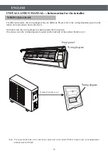
Note: For some models the wires has been connected to the main PCB of indoor unit by manufacturer
without terminal block.
For different models, the wiring diagram may be different. Please refer to the wiring diagrams pasted on the
indoor unit and outdoor unit respectively.
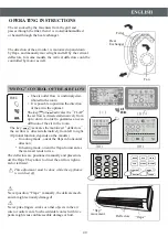
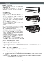
On indoor unit, the wiring diagram is pasted under the front panel;
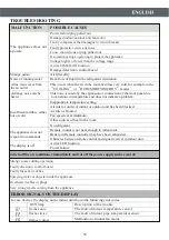
On outdoor unit, the wiring diagram is pasted on the backside of the outdoor handle cover.
Front panel
Wiring diagram
Wiring diagram
Outdoor handle cover
Summary of Contents for HT-07
Page 1: ......
Page 2: ......
Page 3: ... 3 6 7 9 10 12 17 18 28 29 27 2 ...
Page 4: ...3 ...
Page 5: ...4 ...
Page 6: ...5 ...
Page 8: ...7 No 1 2 3 4 5 1 2 5 3 4 1 2 3 4 5 1 2 4 5 3 1 2 3 4 5 3 1 2 3 5 4 3 4 2 1 2 4 5 ...
Page 18: ...2 1 3 17 2 1 3 NO NO Íàãðåâàíèå Îõëàæäåíèå Îñóøåíèå Íàãðåâàíèå Îõëàæäåíèå Îñóøåíèå ...
Page 26: ...25 ...
Page 28: ...27 Ô ð ð èëüò ï îòèâ ïûëè ...
Page 29: ...28 ...
Page 30: ......
Page 59: ......
Page 60: ......
Page 61: ......
Page 62: ... ...
Page 63: ......
Page 64: ......


