background image

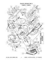
H.E.R.O. INDUSTRIES LTD.                      

330SES / 330SEL MANUAL - “B” VERSION 

23 

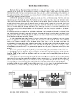
1.     Remove hydraulic feed line, (ref# 62) from hydraulic intake valve, (ref# 60) and also remove hydraulic 
        return line, (ref# 69) from the pressure control valve, (ref# 70). Plug lines to minimize oil loss. (Hint; 
        golf tees work well for this) 
2.     Remove the bolts, (ref# G) passing through the side frames, (ref# 104,106), into the crossblock,  
        (ref# 105). 
3.     Place a drain tray under cylinder area. 
4.     Grasp the pump assembly, and pull away from the piston. Stop when piston pulls free, to allow the 
        hydraulic oil to drain into pan. Completely remove pump assembly from between side frames. 
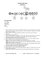
5.     If only replacing piston seals, (ref# 86) continue at step 15. 
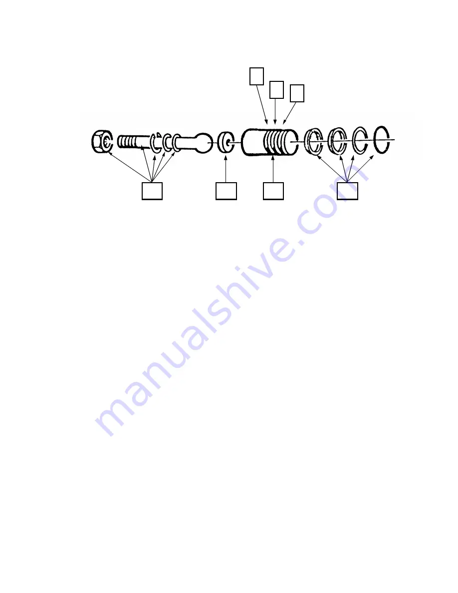
6.     Remove the piston, (ref# 85) from eccentric bearing, (ref# 92). Move to clean work bench for repairs. 
7.     Remove piston circlip, using circlip pliers. Remove piston from rod. 
        

NOTE:

 Use


extreme caution not to damage circlip or the internal circlip groove of piston.  


NOTE:

 Piston rod circlip, washer, o-ring, and nut are not available individually. Parts are available 

        with the purchase of piston rod, (ref# 89) only.  

        NOTE: 

The circlip will have one sharp edge and one smooth edge. The smooth edge should be towards 

        the washer. If reversed, the rod will continually pull out of the piston.  
8.     Remove bronze piston rod seat, (ref# 88) from piston, (ref# 87). 
9.     Examine all parts for wear or damage. Replace as required. 
10.   Fill the center cavity of piston rod seat until flush with grease. Slide seat into piston with concave side 
        (filled with grease) facing out. 
11.   Lightly grease the ball end of piston rod. Push piston rod into piston until ball end of rod contacts seat. 
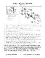
89 

88 

87 

86 

                                                   PISTON REPAIRS 
                                                           (REF# 85)


TOOLS REQUIRED 

-1/2" wrench 
-11/16" wrench 
-circlip pliers 
-torque wrench 
-grease 
-vise grips 

Summary of Contents for 330SEL

Page 1: ...AND MAINTENANCE INSTRUCTIONS AND PARTS LIST Do Not attempt to operate this machine until you have read and understand ALL safety precautions and operating instructions Equipment and chemicals when use...

Page 2: ...ective manufacturers Warranty claims must be made directly to such manufacturers or their local authorized service depots The warranty is only applicable to the original purchaser and the equipment ha...

Page 3: ...THE FOLLOWING SAFETY OPERATING AND MAINTENANCE INSTRUCTIONS ARE IMPORTANT Read and understand this manual completely especially with regard to all safety precautions Read and follow instructions on a...

Page 4: ...un trigger in LOCKED position with gun locked closed NEVER operate the sprayer without the tip guard complete and in place NEVER spray any material in the vicinity of open flame pilot lights electrica...

Page 5: ...or at least 3000 psi working pressure in the spraying system ALWAYS use accessories and components supplied by H E R O Industries or specifically approved in writing by H E R O Industries on with the...

Page 6: ...ly can be dangerous Your H E R O airless sprayer has been fully factory tested prior to shipment BEFORE STARTING YOUR H E R O PUMP CHECK to ensure that the shipping seal has been removed from under th...

Page 7: ...an extension cord you MUST use a 12 3 wire grounded cord up to 50 feet or 10 3 wire grounded cord up to 100 feet DO NOT EXCEED 100 FEET OF EXTENSION CORD If distance is greater purchase and install a...

Page 8: ...alve 7 Trigger gun into paint container until thinner comes through See special notes from step 4 Re direct flow into waste container and continue spraying until thinner runs clear Heavily soiled thin...

Page 9: ...least three times the maximum draw of the motor under full load A minimum 50 and a maximum of 300 of airless spray hose may be used NOTE 50 x 3 8 paint hose part 117 should be used for every 50 x 1 4...

Page 10: ...alves or plugging the tip Always strain the paint before putting through the pump 2 Always spray at the lowest pressure setting which will provide a uniform spray fan fig 1 page 10 Adjust pressure con...

Page 11: ...H E R O INDUSTRIES LTD 330SES 330SEL MANUAL B VERSION 10 AIRLESS SPRAY PAINTING SUGGESTIONS AND TECHNIQUE Poor Good Tailing Good Pattern Fog Overspray FIG 1 FIG 2 FIG 2 FIG 3 FIG 4 FIG 5...

Page 12: ...ay tip s fan width classification This size is measured in inches and is determined when spraying 12 inches from the spray surface Various methods of noting the fan widths are used by tip manufacturer...

Page 13: ...apulse membrane is to create a barrier between the hydraulic oil and the spray material and transfer the energy created To fully understand and trouble shoot a H E R O pump always keep in mind that fo...

Page 14: ...own as the pressure control valve is used to control the units operating pressure The valve is fully adjustable from 0 psi to 3000 psi By turning the pressure control valve knob ref 71 clockwise the p...

Page 15: ...paint left in the pump and hose at the completion of a job When the prime valve is open the material is pumped through the paint intake and outgo and back to the source by way of the prime valve When...

Page 16: ...rred to as the Hydrapulse membrane Test The solution to almost all problems can be found in the paint side valves due to the increased wear from contact with the abrasive paint spray materials Intake...

Page 17: ...e the seating surface Inspect for foreign material jamming ball Replace parts as needed 3 Intake seat loose bypassing remove intake endcap ref 9 and ball guide ref 16 Inspect inlet washer ref 10 for e...

Page 18: ...tire hydraulic system must be cleaned and flushed Make sure to remove and clean the hydraulic tank screen ref 63 during this process Refill only with genuine H E R O LVO hydraulic fluid NOTE If lacque...

Page 19: ...e valve return hose ref 50 for material bypass Repair prime valve using ref 41 if material is bypassing LOW STATIC PRESSURE LOW SPRAY PRESSURE Check with pressure gauge see page 15 for details 1 Press...

Page 20: ...eck all fittings and hose clamps in intake assembly for tightness 2 Air leak in paint intake check for cracked or broken intake fittings Swivel connector ref 8 or hose barb ref 6 may be damaged due to...

Page 21: ...Plugged siphon screen siphon tube gun filter or a combination inspect and clean or replace as required 4 Plugged tip remove and clean tip 5 Pump malfunctioning or unsuitable for the material refer to...

Page 22: ...ad the jam n u t onto the stem 4 Tighten the jam nut until a measurement of 1 5 16 is obtained T he measurement is taken from the top of the hydraulic horn ref 53 to the top of the spring locator ref...

Page 23: ...ds hydrapulse membrane 10 Place the spring ref 14 into the ball guide so the smaller end of the spring will contact the ball 11 Assemble the ball guide with spring onto the endcap over the already ins...

Page 24: ...7 Remove piston circlip using circlip pliers Remove piston from rod NOTE Use extreme caution not to damage circlip or the internal circlip groove of piston NOTE Piston rod circlip washer o ring and nu...

Page 25: ...e flat washer one side h as a contoured face into groove C then place o ring in front of flat washer so that it fits into the contoured face of the flat washer 18 Place one cup washer into groove B wi...

Page 26: ...hould be open so that it drags down the sides of the tunnel during installation If closed too much it will trap the ball and cause pulsation in spray pattern 11 Place ball into cage 12 Install seat be...

Page 27: ...al Tighten 1 4 turn past finger tight If leakage occurs at this junction point during operation tighten 1 4 turn more or until leakage stops To install new valve stem or valve stem seals ref 42 or 43...

Page 28: ...place Inspect retainer for wear The retainer has a small locating hole in it The hole should be flush or slightly beveled The greater the wear on the ball seat and retainer the poorer the s tatic pres...

Page 29: ...Pole 10 55 7302 2 Maxi Pole 10 55 2412 12 Mini Pole 10 55 7303 3 Maxi Pole 10 55 2418 18 Mini Pole 10 55 7306 6 Maxi Pole 10 55 2424 24 Mini Pole 10 55 7309 9 Maxi Pole 10 55 013 2 300 Gun 1710 Flip 2...

Page 30: ...serial 780651 760381 1 18 5V Intake O RING VITON 1 19 4 02 22 2501B Intake HEAD MATERIAL NEW After serial 780651 760381 1 20 02 22 2004 Intake CUSHION MATERIAL HEAD 1 21 4 6658B Intake REPAIR KIT REF...

Page 31: ...OW 3 60 4 30 Hydraulic INTAKE VACUUM VALVE 1 61 31 1 Hydraulic METERING ORIFICE 1 62 4 31 Hydraulic FEED LINE COMPLETE C W REF 60 1 63 4 45 1 Hydraulic TANK SCREEN 1 64 45 4 Hydraulic ELBOW RETURN 1 6...

Page 32: ...98 66 100 Drive BELT 1 99 4 48 100 Drive SHEAVE MOTOR C W SET SCREWS 2 1 100 4 61 74 Drive MOTOR 1 0 H P C W SWITCH CORD 1 101 NOT USED 102 65 102M Drive ON OFF SWITCH MARATHON MOTORS ACC 103 NOT USED...

Page 33: ...E HW1050P CAPSCREW HX HD GR 5 5 16NC X 1 2 PLATED F HW1055 LT CARRAGE 5 16 X 5 8 PLATED G HW1060P CAPSCREW HX HD GR 5 5 16NC X 3 4 PLATED H HW1070F CAPSCREW HX HD FULL THRD 5 16 X 1 1 4 J HW1087 CAPS...

Page 34: ...ES LTD 330SES 330SEL MANUAL B VERSION 33 PARTS SCHEMATIC 330SES 330SEL 119 118 123 120 121 112 111 114 116 115 122 1 6 51 50 4 5 2 5 7 125 124 8 126 129 130 330SEL D Z V CC Z Y D Q C P Z P Z P D E D K...

Page 35: ...13 10 11 J X 9 A 52 53 54 55 R 56 57 59 58 60 61 AA B 105 86 85 89 87 88 62 23 32 31 35 49 20 106 G AA 107 BB DD AA E 107 70 69 59 66 65 64 68 E AA C 63 67 108 90 F 91 92 93 100 M M 96 H S 110 99 96...

Page 36: ...KE CITY WAY BURNABY B C CANADA PHONE 604 420 6543 800 494 4376 FAX 604 420 8725 PURCHASED FROM __________________________ __________________________ __________________________ ________________________...

Reviews: