


H.E.R.O. INDUSTRIES LTD.
330SES / 330SEL MANUAL - “B” VERSION
6
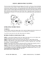
SETTING UP TO SPRAY
1
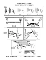
Remove unit from shipping carton.
2
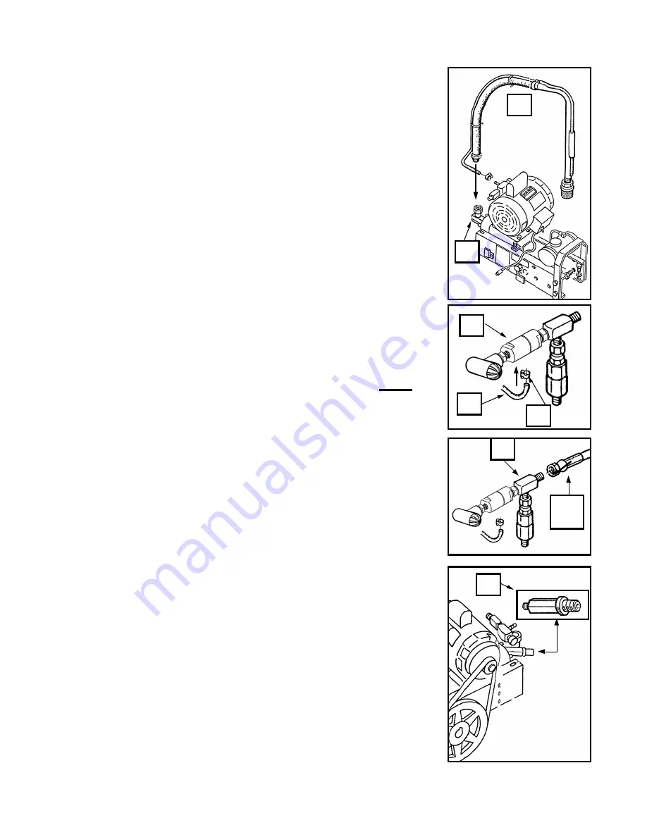
Attach intake siphon assembly (ref# 7) to intake elbow (ref# 8). Use
caution to avoid over tightening which may result in cracked or broken
fittings.
3
Attach prime hose (ref# 50) to prime valve (ref# 49). Secure with clamp
(ref# 51).
4
Attach paint hose to outgo tee (ref# 35).
5
Attach gun to paint hose.
NOTE
;
Spray tip and tip guard should be
attached to gun prior to attaching to hose
.
6
Place intake siphon assembly into a clean 5 gallon pail.
7
Install strainer bag (accessory item 5GAL SB) in pail and secure with large
rubber band ( accessory item 106).
NOTE
;
Strainer
bag must remain 4
inches from the bottom of pail
8
Trigger gun to release any pressure in the unit. Use extreme caution to
ensure that the gun is not directed towards anyone or any object which may
be damaged.
NOTE
;
Unit may contain storage solution
.
9
To remove storage solution, add one gallon of thinner, compatible with the
type of paint to be used, to the siphon pail.
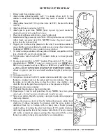
10 Turn pressure control knob (ref# 71) counter clockwise to lowest pressure
setting.
11 Be sure motor switch is in "OFF" position. Plug unit into 115V, 15 amp.,
grounded circuit.
NOTE;
If using an extension cord, you
MUST
use a
#12/3
wire grounded cord, up to
50
feet or
#10/3
wire grounded cord, up
to
100
feet.
DO NOT EXCEED 100 FEET OF EXTENSION CORD.
If
distance is greater, purchase and install additional lengths of airless spray
hose
.
12 Turn motor switch "on".
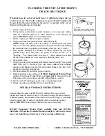
13 Turn prime valve knob (ref# 45) counter clockwise until fully open. Allow
thinner to circulate back into the siphon pail for a few minutes. Then turn
the prime valve knob clockwise to close the valve ( close tightly ), and
direct the flow to the paint hose and gun. Leave the pressure setting low.
14 Trigger gun into waste container.
15 Pour paint through strainer bag into siphon pail.
16 Repeat steps 13 and 14, until paint flows freely.
NOTE
;
Never turn prime
valve back to "prime" position when the unit is under pressure
.
17 Spray a test pattern. Begin by spraying a test pattern onto old newspaper or
other scrap material.
18 Increase the pressure, slowly at first, by turning the pressure control knob
clockwise. Continue increasing the pressure until the spray pattern is
uniformed from top to bottom, with no heavy areas. Secure pressure
control setting, by turning the silver lock ring (ref# 72) counter clockwise
until snugly against the face of the pressure control knob.
If
heavy areas are
still visible at maximum pressure setting, thin the paint with the correct
thinner, according to the paint manufacturer's recommendations.
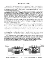
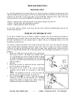
7
8
Paint
Hose
35
70
49
51
50


