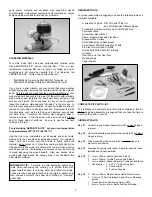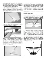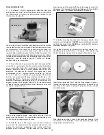
As mentioned earlier, we used the Hitec
™
#54403 after-market
micro switch assembly for this model. You can certainly use a
standard switch assembly but these are typically much bulkier and
weigh more - your call.
❑
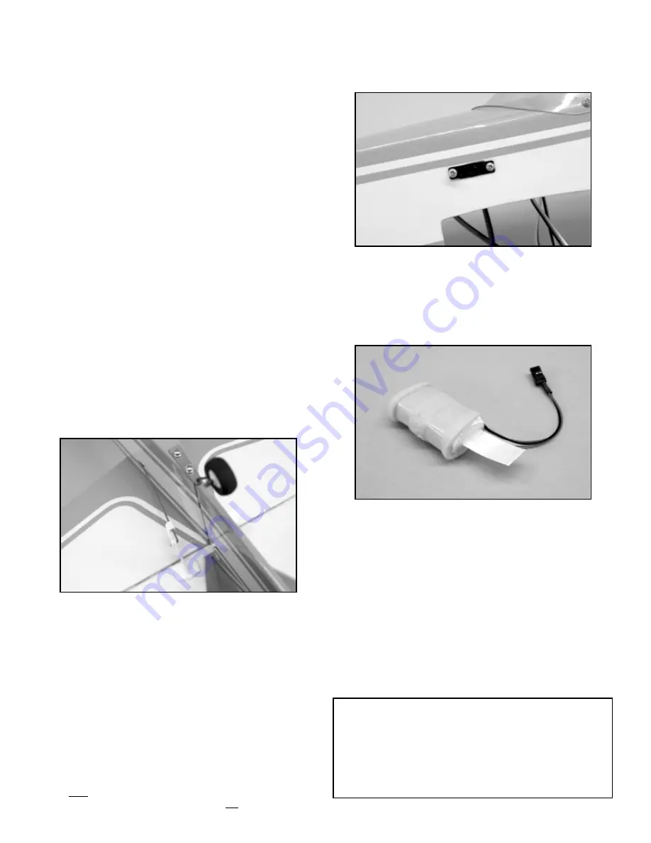
6) The battery pack is installed into the fuselage through the
wing saddle and placed into the space directly beneath the fuel
tank. In order to make the pack a little more easily removable, we
first wrapped it with a little filament tape, forming a "tab" at one
end. When the pack is inserted into the space beneath the tank,
the tab is left hanging out of the opening. This allows you to
remove the pack if ever necessary.
❑
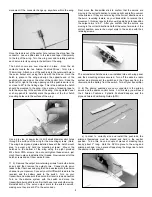
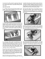
7) The receiver is now installed into the fuselage. First make
each of the servo connections to the appropriate receptacles in
the receiver. Also plug the switch connector into the receiver.
Wrap the receiver in foam and place it into the forward
compartment, just behind the fuel tank.
For battery charging
purposes, leave the switch connection to the battery pack
accessible within the fuselage.
Likewise, leave the 6" aileron
servo extension lead out and accessible within the fuselage for
easy connection to the aileron "Y"-harness. Use additional small
pieces of foam to wedge the receiver within the compartment.
The receiver antenna is now routed out of the fuselage and back
to the rear of the airplane. To do this, drill a small hole in the side
of the fuselage to exit the antenna. Secure it at the rear of the
fuselage with a small hook and a rubber band.
Re-install the output arm retaining screw in the throttle servo.
Reassemble the muffler and needle valve back onto the engine.
Trim the silicon fuel tubes to fit onto the carburetor and muffler
pressure nipple. Be sure to leave enough slack to easily grip
these tubes for fueling purposes.
❑
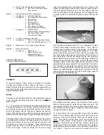
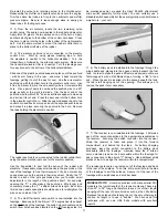
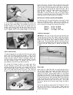
3) From the kit contents, locate the two remaining nylon
control horns. These are now mounted to the rudder and elevator.
Apply thick CA glue to the two spikes on one of the horns. Apply
another dab of glue to the bottom of the control horn base. Press
the horn in place, into the holes in the bottom of the right elevator
half. Use the same method to mount the rudder control horn in
place to the bottom left side of the rudder.
❑
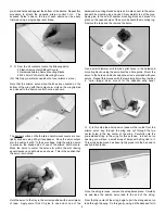
4) The elevator pushrod is now connected to the elevator
control horn.
Start by using pieces masking tape to hold
the elevators in neutral to the horizontal stabilizer.
Turn the
transmitter on, followed by the airborne radio system. Make sure
the transmitter elevator trim is in neutral. Turn the fuselage over
for easy access to the bottom of the horizontal stabilizer.
Slide one of the plastic pushrod keepers in place onto the pushrod
- with its arm facing to the rear - and move it back toward the
fuselage, getting it out of the way for now. Line the wire elevator
pushrod up with the bottom hole in the elevator control horn. Use
a fine tip marker to mark the wire exactly where it intersects this
hole. Use a pair of pliers to now bend the pushrod wire to a 90
O
angle, exactly at the mark just made. Trim the bent end of the
pushrod wire to within 3/16" and use a little sandpaper to clean up
and burrs at its cut end. Press the bent end into the bottom hole
in the elevator control horn. Slide the pushrod keeper back to the
control horn and flex its arm up and over the exposed pushrod end
and press it in place, securing the pushrod to the horn. Remove
the tape holding the elevators in neutral.
The rudder pushrod is now connected to the rudder control horn,
using the same method just used for the elevator pushrod.
Use the transmitter to now test the action of the rudder and
elevators. If necessary, make small bends in the pushrods, at the
rear of the fuselage, to free their movement. You do not want any
undue pressure on the servos in their movement. Finally, the "V"
bends in each of the wire pushrods allow you to make small
adjustments in the length of the pushrods itself. For example,
opening the "V" a little makes the pushrod a little longer and
conversely, closing the "V" a little shortens its length. Each time
this is done, needle nose pliers should be used to re-straighten the
wire on each side of the "V".
❑
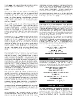
5) The On/Off airborne radio switch is now installed into the
fuselage. Because both the Norvel
™
.074 engine has its exhaust
on the right side of the fuselage, the switch mount doubler and its
switch lever hole have been located on the left fuselage side. As
11
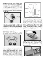
MODELER'S TIP: A common problem with many smaller R/C
models is the typical length of the receiver antenna. These are
often 30" to 36" long and therefore leave a lot of their length
hanging off the rear of a small model, such as the Little Extra.
Because the antenna should never be cut, the only other way to
shorten its length is to use a "bobbin". We have used this
technique with our own Little Extra models with excellent
results.


