5
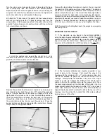
movement if the connector hangs up anywhere within the wing.
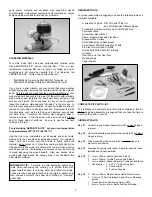
Once the lead is out of the center hole, remove the string from the
connector. Leave a little slack in the lead and tape it temporarily
to the top of the wing. Turn the wing over and carefully position
each servo into its opening in the bottom of the wing.
The hatch covers are now mounted in place.
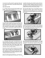
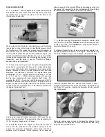
From the kit
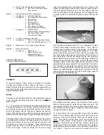
contents, locate the two Aileron Pushrod Wires - 1mm dia. x
126mm long. Attach one of the pushrods to the outermost hole in
the servo output arm, using the end with the Z-bend. Hold the
hatch in place in the wing and align the opposite end of the
pushrod with one side or the other of the control horn. Slide the
hatch left or right in the wing opening until the pushrod wire is at,
or close to 90
O
to the trailing edge. This is the position the hatch
should be mounted to the wing. Use a piece of masking tape to
hold the servo tray to the surface of the wing. Use a pointed dowel
or sharp pencil to carefully mark the position of the four hatch
mounting holes onto the surface of the wing.
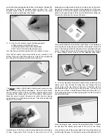
Use a pin vise or power tool to drill small diameter pilot holes
through the surface of the wing for the mounting screws (Note:
The wing has plywood plates installed beneath the hatch mount
area to accept and hold the mounting screws).
Mount the
hatches to the bottom of the wing using the eight provided
M2 x 5mm PWA screws - do not over-tighten these screws, just
cinch them in place to establish the threads. Now remove all of the
hatch screws and set them aside for now.
❑
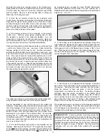
5) Remove the output arm retaining screws from both aileron
servos and then remove the output arms. Connect both servo
leads to the Y-harness and plug the Y-harness lead into the aileron
channel in your receiver. Connect your On/Off switch lead into the
receiver and the battery pack to the switch.
Turn on your
transmitter and make sure the aileron trim lever is in dead neutral.
Turn on the airborne system with the switch and move the
transmitter aileron stick to confirm that he servos are both moving.
Reinstall both of the servo output arms to the aileron servos,
making sure they are at 90
O
to the servo body.
Next, move the transmitter stick to confirm that the servos are
moving in the correct direction to produce right and left movement
to the ailerons. If they are not moving in the correct directions, use
the servo reversing feature on your transmitter to reverse their
movement - this may require that you will again have to reposition
the output arms to 90
O
. After you confirm that the servos are
moving in the correct direction and that the output arms are in the
correct position, secure the output arms to the servos with their
retaining screws.
The servos/servo hatches are now installed into each wing panel
and their mounting screws secured. Turn off the airborne radio
system and disconnect the switch and the Y-harness from the
receiver and the battery from the switch. Turn off your transmitter.
❑
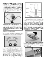
6) The aileron pushrods are now connected to the aileron
servos and the aileron control horns. For this step you will need
the 2 Aileron Pushrods, 2 plastic Pushrod Keepers, and the
plywood Aileron Positioning Guide (APG).
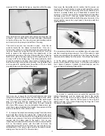
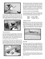
a) In order to correctly size and install the pushrods, the
ailerons themselves must be placed and held in the neutral
position. To do this, have a couple of pieces of masking tape
handy, about 3" long. Hold the APG in place to the wing and
aileron as shown. Use a piece of tape along the hinge line to hold
the aileron in this position.


