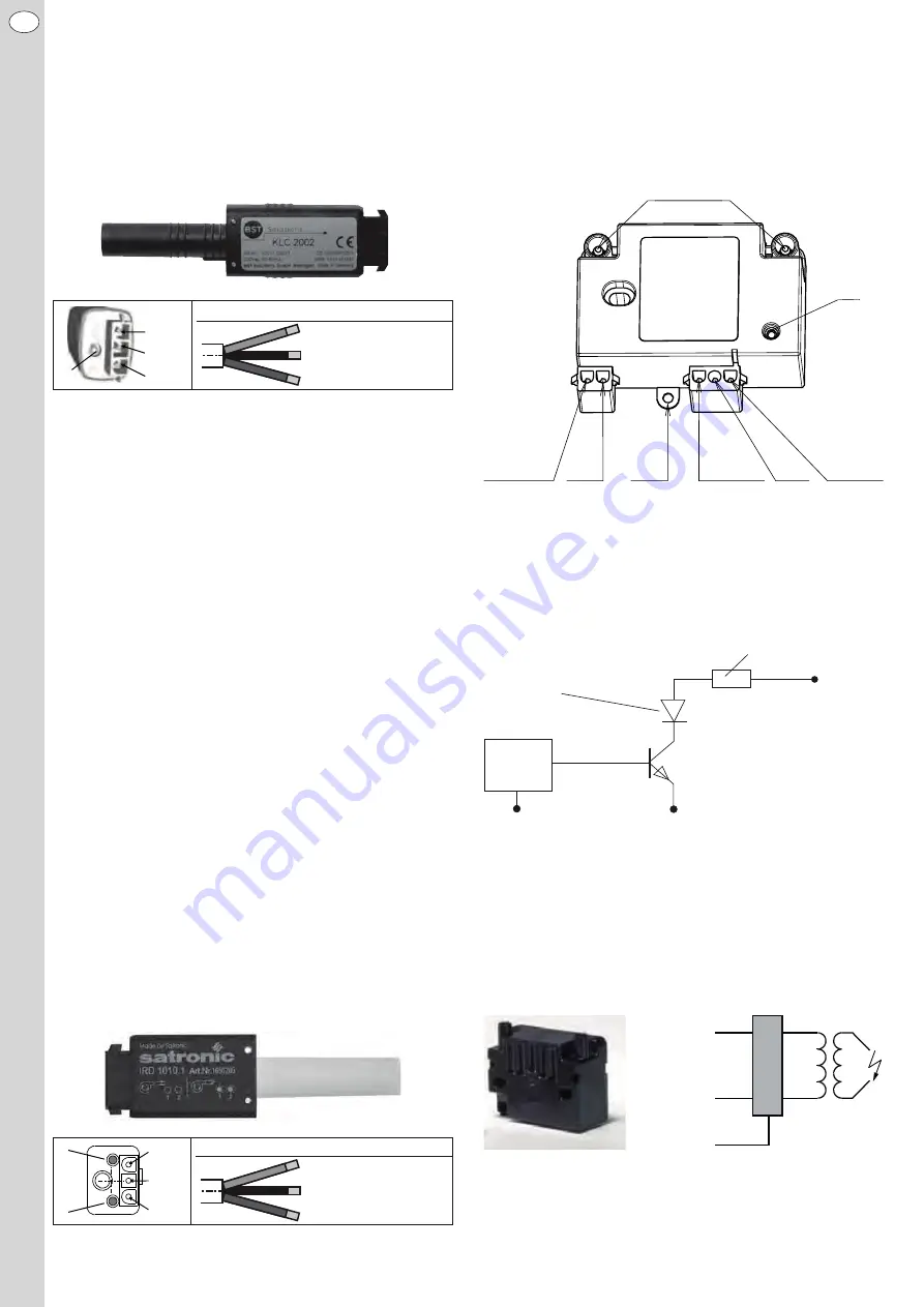
The LED may additionally be used as an optical interface to read different
performance parameters (such as e.g. pulse counter, visualisation of the
flame’s signal intensity, serial number). In order to prevent, at very extreme
energy densities, that the characteristic flickering signals of the flame will
be interfered by the emitting radiation of the recirculation tube and other
glowing components, an optical filter precedes the real light sensor. It
dims the appearing radiation in the background in a partial region of the
spectrum so that the usable flame signal appears comparatively stronger.
Misinterpretations that under extreme conditions can also lead to unsafe
operating conditions are also avoided.
BST Solutions KLC 2002 flame detector.
Optical flame detector, IRD 1010.1
Like the KLC 2002, the principle of the IRD 1010.1 optical flame detector
(by Honeywell) is based on the detection of the alternating part of the in-
frared radiation emitted from the flame. However, the separation between
the direct and alternating components of the radiation is lower resoluted
in comparison with the sensor KLC 2002. A proportion of radiation with a
constant frequency may also be misinterpreted as flame. A flame rupture
on a very strongly glowing re-circulation pipe will be deteced a bit later
due to the combined effects towards the KLC 2002 flame detector. The
use of the IRD 1010.1 flame detector in connection with the LOA 24 firing
unit by Siemens has been approved in accordance with EN230:1991.
There is no approval in connection with the LMO 14 firing unit. Therefore
this combination is not deliverable.
The infrared cell and the pre-amplifier of the IRD 1010.1, together with the
evaluation electronics, are integrated in the housing of the flame detector.
On the rear side of the housing of the IRD 1010.1 flame detector are two
LED’s for the status display, as well as a setting screw for adjustment of
the sensitivity.
Adjustment of the sensitivity of the IRD 1010.1 flame detector
LED 1 has the function of a warning diode. A secondary light is available
if LED 1 is lighting up or flickering during the pre-ventilation. If such fli-
ckering occurs during the operation of the burner this means that the
flame signal is too weak. LED 2 indicates the respective switching state
of the flame detector (ON: flame signal is emitted; OFF: no flame signal
emitted).
For adjusting the sensitivity of the IRD 1010.1 to the respective operational
conditions we recommend the following procedure:
Prior to putting the burner into operation you should first set the adjust-
ment screw for the sensitivity of the flame detector to the maximum value
(scale value 7). After starting the burner successfully carefully turn back
the adjustment screw until LED 1 is flickering. Subsequently the sensitivity
is increased so that both LED’s are lighting up. You should then start the
burner again. You should check that LED 1 is not flickering during the pre-
ventilation. For safety reasons make sure that the sensitivity is not adjus-
ted higher than necessary.
Both LED‘s ON:
burner in operation
Both LED‘s OFF:
burner in pre-ventilation
Honeywell IRD 1010.1 flame detector
Accumulation of cables
Blue
Black
Brown
L E D
Black, switching output, FL
Brown, power supply, L1
Blue, N
Accumulation of cables
L E D 1
L E D 2
Black, switching output, FL
Brown, power supply, L1
Blue, N
1 1
2 2
3 3
4 4
5
5
6
6 7
1 1
2
Blue
Black
Brown
Electrical ignition unit with integrated ionisation flame monitoring,
ZTÜ
At the electrical ignition unit with ionisation flame monitoring ZTÜ (Beru)
one of the two existing ignition electrodes is used as an ionisation elect-
rode to monitor the flame.
For evaluation of the signal a circuit element, similar to the optical flame
detector, is integrated inside the ignition unit that displays the presence
of a flame through a high/low signal. As a result the ignition unit with flame
monitoring, as well as the optical flame detector, are usable with the same
burner control.
An LED in the housing of the ignition unit indicates the operating state of
the ionisation flame monitoring:
LED is OFF:
Ionisation flame monitoring is carrying no cur-
rent or faulty electrical connection.
LED is flashing:
Ionisation flame monitoring is active, no flame
has been detected.
LED is permanently ON:
Ionisation flame monitoring is active, flame
has been detected.
Output wiring of BST Solutions KLC 2002 flame monitor/Beru ZTÜ /
Honeywell IRD 1010.1
2.5 Ignition device
If an optical flame detector is used the ignition of the mixture occurs
through a separate ignition device (Danfoss EBI 4). An earth connection
is located in the primary connection socket to achieve a low electro-mag-
netic interference emission, i.e. the connection socket has three-pole
(phase, neutral wire and earth). Consequently the lateral earth lug, that is
used at the ignition unit with integrated flame monitoring is absent.
2.6 Oil firing unit
The control and monitoring of the burner occurs alternatively by an elect-
romechanical oil firing unit, Siemens LOA 24 (approval according to DIN
EN 230:1991), or by an electronic oil firing unit, Siemens LMO 14 (approval
High voltage
Blue,
N
Blue,
N
PE,
Earthing
Brown,
voltage
supply, L1
Black,
switching
output,
FL
LED
Brown,
Ignition
"ON": 230 V AC
"OFF": 0 V
Brown, power supply, L1
Black, switching output, FL
“Digital signal“
When applying the voltage:
- Flame OFF, no potential, “high“
- Flame ON, “low“
With the alternating voltage at FL the signal is
rectified through the transistor, and the diode
is connected in series as well (to enable a
connection to the burner control unit with ionisation
flame monitoring).
Blue, N
Signal
Electronic strobe
Flame sensor
Series resistor to protect the transistor
Electronic control
at the flame
sensor
Blue, GND
Brown,
voltage supply, L1
Ignition
"ON": 230 V AC
"OFF": 0 V
PE, Earthing
50/60 Hz
20 kHz
26
EN


