background image

56

FR

9.

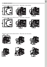
Dimensions du brûleur

HL 60 GLV.2-S / ILV.2-S / KLV.2-S  –  Bride coulissante 

HL 60 GLV.2-S / ILV.2-S / KLV.2-S  –  Bride unitaire

HL 60 GLV.2-S / ILV.2-S / KLV.2-S  –  Bride coulissante 

HL 60 GLV.2-S / ILV.2-S / KLV.2-S  –  Bride unitaire 

Summary of Contents for HL 60 GLV.2-S

Page 1: ...uciatore gasolio www herrmann burners de DE Technische Information Montage und Betriebsanleitung EN Technical information Assembly and operating instructions FR Caract ristiques techniques Instruction...

Page 2: ...echnische Information Montage und Betriebsanleitung Technical information Assembly and operating instructions Caract ristiques techniques Instructions de montage et de service Informazioni tecniche Is...

Page 3: ...drucksteife Gebl se garantiert einen pulsationsfreien Start des Brenners Dank weiterer qualitativ hochwertiger Komponenten ist ein zuverl ssiger Betrieb des Brenners ber eine lange Lebensdau er siche...

Page 4: ...assification 3 the German Envi ronmental Label Blue Angel in accordance with RAL UZ 9 and the Swiss Ordinance on Air Pollution LRV The extremely pressure stiff blower designed specifically for the com...

Page 5: ...ection de l air OPair La ventilation extr mement rigide la pression sp cialement con ue pour la combustion du fioul garantit un d marrage du br leur sans pulsation Gr ce d autres composants de haute q...

Page 6: ...emamente resistente alla pressione progettato speci ficamente per la combustione di olio combustibile garantisce un avvio senza pulsazioni del bruciatore Grazie ad altri componenti di alta qua lit si...

Page 7: ...otor Hanning O1A095 055 lpumpe Danfoss BFP 21 L3 LE lvorw rmer Danfoss FPHE LE PTC 50 Z ndeinheit Danfoss EBI 4 Beru ZT mit Flammen erkennung Flammen berwachung Honeywell IRD 1010 1 rot axial BST Solu...

Page 8: ...d flie t der gesamte Brennstoffstrom ber das Druckregelventil zu r ck in den Vorratstank Zur Brennstoffeinspritzung wird das Magnetventil bestromt und damit ge ffnet Der Brennstoff gelangt daraufhin m...

Page 9: ...nd wird die Empfindlichkeit wieder soweit erh ht dass beide LED leuchten Danach muss der Brenner erneut gestartet werden Dabei muss berpr ft werden dass LED 1 w hrend der Vorbel ftung nicht flackert A...

Page 10: ...permanent rot Dieser Zustand bleibt auch bei Netzspannungsunterbrechung erhalten Der elektronische Feuerungsautomat LMO14 verf gt zudem ber eine visuelle Betriebsanzeige und St rursachendiagnose welc...

Page 11: ...m betrieben oder einem Zweistrangsystem betrieben werden Serienm ig ist der Brenner auf Zweistrangsysteme voreingestellt Bei der Umstellung der Pumpe auf Einstrangbetrieb muss der R cklaufstutzen mit...

Page 12: ...schl uche in eine gelochte Gummit lle eingelegt die wiederum in die Ausnehmung der Grundplatte eingesetzt wird Die jeweils nicht benutzte Ausnehmung der Grundplatte wird mit einer ungelochten T lle Bl...

Page 13: ...n gr e und dem am Druckregler der l pumpe eingestellten Einspritzdruck Durch Drehen der Stell schraube im Uhrzeiger sinn erh ht sich der l druck und damit der eingespritzte lmas senstrom Umgekehrt ver...

Page 14: ...60 80 100x150 24 10 0 5 4 23 4 4 5 2 5 2 5 HL 60 KLV 2 S 26 2 19 0 60 80 100x150 24 11 0 6 3 27 4 4 5 2 5 2 5 HL 60 KLV 2 S 27 2 28 0 60 80 100x150 24 11 2 6 5 28 4 4 5 2 5 2 5 HL 60 KLV 2 S 28 2 36 0...

Page 15: ...N 6 h 1 2 nur bei LMO 14 A1 Siemens LOA 24 LMO 14 gr n braun gelb wei 31 32 N 3 R Nachlaufrelais TR 120 1 L N S schwarz blau braun 12 11 1 1 2 3 braun gelb gr n blau 4 N 1 2 V blau gelb gr n braun N 3...

Page 16: ...15 DE 7 Explosionszeichnung mit Ersatzteilliste...

Page 17: ...itflansch Dichtung N P Unit 10006 00062 3 Brennerrohr N P Unit 10005 00078 4 Dichtung f r Brennerrohr N P Unit 10006 00058 5 Unitflansch geneigt N P Unit 10002 00121 6 O Ring 99x4 Viton 10006 00059 7...

Page 18: ...itig und Unitflansch 10023 00020 Zylinderkopfschraube mit Innensechskant SW4 hnl DIN 912 M4x18 f r Abdeckung 10023 00184 Senkschraube mit Kreuzschlitz DIN 965 M3x5 f r Haltering Dichtung 10023 00043 Z...

Page 19: ...e defekt lpumpe austauschen Parafinausscheidungen 4 C K ltesicher verlegen Heiz l nicht mehr fliessf hig 1 C K ltesicher verlegen 5 Magnetventil Magnetventil ffnet nicht Spule des Magnetventils defekt...

Page 20: ...V 2 S KLV 2 S NLV 2 S PLV 2 S Grundplatte Schiebeflansch HL 60 GLV 2 S ILV 2 S KLV 2 S NLV 2 S PLV 2 S Grundplatte Unitflansch HL 60 GLV 2 S ILV 2 S KLV 2 S NLV 2 S PLV 2 S Grundplatte Mini Unitflansc...

Page 21: ...20 DE 9 Brennerabmessungen HL 60 GLV 2 S ILV 2 S KLV 2 S Schiebeflansch HL 60 GLV 2 S ILV 2 S KLV 2 S Unitflansch HL 60 GLV 2 S ILV 2 S KLV 2 S Schiebeflansch HL 60 GLV 2 S ILV 2 S KLV 2 S Unitflansch...

Page 22: ...21 DE HL 60 NLV 2 S PLV 2 S Schiebeflansch HL 60 NLV 2 S PLV 2 S Unitflansch HL 60 NLV 2 S PLV 2 S Schiebeflansch HL 60 NLV 2 S PLV 2 S Unitflansch 9 Brennerabmessungen...

Page 23: ...des Gebl senachlaufes bieten wir zwei ver schiedene Nachbel ftungssysteme an Feuerungsautomat Siemens LMO64 Eine elegante Art den Brenner mit der Nachbel ftungsfunktion auszustat ten stellt der Einsat...

Page 24: ...en Heiz lmenge sowie der Brennerlaufzeit bieten wir den Einbau einer Kombination aus ldurchlauf und Betriebs stundenz hler an Der Einbau des ldurchlauf und Betriebsstundenz h lers kann werksseitig erf...

Page 25: ...nning O1A095 055 Oil pump Danfoss BFP 21 L3 LE Oil pre heater Danfoss FPHE LE PTC 50 Ignition Danfoss EBI 4 Beru ZT with flame monitoring Flame control Honeywell IRD 1010 1 red axial BST Solutions Wid...

Page 26: ...ly opened The reupon the fuel reaches the nozzle due to the adjusted pressure at the pressure control valve In order to reduce the start up and switch off emissions the bur ner has been equipped in se...

Page 27: ...eased so that both LED s are lighting up You should then start the burner again You should check that LED 1 is not flickering during the pre ventilation For safety reasons make sure that the sensitivi...

Page 28: ...vent of in terruption of the mains voltage The LMO14 electronic oil firing unit also features a visual operating display and trouble shooting diagnosis that are displayed through the multi co loured L...

Page 29: ...ssure should be 0 1 mbar For pressure boilers you should gather the chimney draught that needs to be adjusted from the boiler operating instructions For operating in room air independent mode the burn...

Page 30: ...he oil hoses have to be insert in a rubber grommet that is insert into the recess of he base plate The recess of the base plate that is not used is respectively sealed by using a rubber grommet withou...

Page 31: ...has been set on the pressure con troller at the oil pump By turning the setting screw clockwise the oil pressure will conse quently increase and also therefore the in jected oil mass flow In the oppos...

Page 32: ...L 60 KLV 2 S 26 2 19 0 60 80 100x150 24 11 0 6 3 27 4 4 5 2 5 2 5 HL 60 KLV 2 S 27 2 28 0 60 80 100x150 24 11 2 6 5 28 4 4 5 2 5 2 5 HL 60 KLV 2 S 28 2 36 0 60 80 100x150 24 11 5 6 7 29 4 4 5 2 5 2 5...

Page 33: ...Siemens LOA 24 green brown yellow white 31 32 N 3 R Post purge relay TR 120 1 L N S black blue brown 12 11 1 1 2 3 LD brown yellow green blue 4 N 1 2 V blue yellow green brown N 3 31 1 3 2 BM M 1 vio...

Page 34: ...33 EN 7 Expanded view with spare parts list...

Page 35: ...00006 2 Gasket for flange unit N P Unit 10006 00062 3 Burner pipe N P Unit 10005 00078 4 Gasket for burner pipe N P Unit 10006 00058 5 Unitflange angular N P Unit 10002 00121 6 O Ring 99x4 10006 00059...

Page 36: ...et head cap screw SW4 similar DIN 912 M4x18 for cover 10023 00184 Countersunk crosshead screw DIN 965 M3x5 for sealing guide ring 10023 00043 Hexagon socket head cap screw SW 4 DIN 912 M4x14 for holde...

Page 37: ...ary filter Defective oil pump gear Exchange oil pump Discharge of paraffin 4 C Install cold insulation Heating oil no longer free flowing 1 C Install cold insulation 5 Solenoid valve Solenoid valve do...

Page 38: ...2 S KLV 2 S NLV 2 S PLV 2 S Base plate Shift flange HL 60 GLV 2 S ILV 2 S KLV 2 S NLV 2 S PLV 2 S Base plate Unit flange HL 60 GLV 2 S ILV 2 S KLV 2 S NLV 2 S PLV 2 S Mini base plate Unit flange 9 Di...

Page 39: ...8 EN 9 Dimensions of the burner HL 60 GLV 2 S ILV 2 S KLV 2 S Shift flange HL 60 GLV 2 S ILV 2 S KLV 2 S Unit flange HL 60 GLV 2 S ILV 2 S KLV 2 S Shift flange HL 60 GLV 2 S ILV 2 S KLV 2 S Unit flang...

Page 40: ...39 EN HL 60 NLV 2 S PLV 2 S Shift flange HL 60 NLV 2 S PLV 2 S Unit flange HL 60 NLV 2 S PLV 2 S Shift flange HL 60 NLV 2 S PLV 2 S Unit flange 9 Dimensions of the burner...

Page 41: ...ope ration conditions we recommend a post run of the blower after the bur ners deactivation To realize the post run of the blower we offer two different post ventilation systems Oil firing unit Sieme...

Page 42: ...e running period of the burner we offer you the installation of a combination of oil flow me ter and operating hour meter The installation of the oil flow meter and operating hour meter may be carried...

Page 43: ...N 14214 1 6 Composants Composant Fabricant D signation mod le Moteur Hanning O1A095 055 Pompe fioul Danfoss BFP 21 L3 LE R chauffeur fioul Danfoss FPHE LE PTC 50 Unit d allumage Danfoss EBI 4 Beru ZT...

Page 44: ...le combustible l lectrovanne est mise sous tension ce qui provoque son ouverture Le combustible parvient ensuite au gicleur la pression r gl e sur la vanne manor gulatrice Pour r duire les missions po...

Page 45: ...ez la sensibilit ce qu il faut pour que les deux LED s allument Puis il faut faire d marrer nouveau le br leur Ce faisant il faut bien v rifier que la LED 1 ne vacille pas pendant la pr ventilation Po...

Page 46: ...verrouill le voyant de d rangement reste constamment allum en rouge Cet tat demeure aussi en cas de coupure de la tension secteur L automate d allumage lectronique LMO14 dispose en outre d un affi ch...

Page 47: ...la fabrication en s rie le br leur a t pr r gl sur les syst mes bi tubes Lors de la conversion de la pompe au mode Monotube il faut obturer l embout de retour avec un bouchon et retirer la vis de con...

Page 48: ...ment sur le c t gauche ou droit de la plaque de base partir du br leur Pour ce faire les flexibles de fioul sont pos s dans une douille caoutchout e perc e qui elle m me est plac e dans l videment de...

Page 49: ...gl e sur le ma nor gulateur Le fait de tourner la vis de r glage dans le sens horaire hausse la pres sion du fioul et donc le flux massique du fioul inject Inversement le fait de tourner la vis de r...

Page 50: ...1 0 60 80 100x150 24 10 0 5 4 23 4 4 5 2 5 2 5 HL 60 KLV 2 S 26 2 19 0 60 80 100x150 24 11 0 6 3 27 4 4 5 2 5 2 5 HL 60 KLV 2 S 27 2 28 0 60 80 100x150 24 11 2 6 5 28 4 4 5 2 5 2 5 HL 60 KLV 2 S 28 2...

Page 51: ...pour LMO 14 A1 Siemens LOA 24 LMO 14 vert marron jaune blanc 31 32 N 3 R Relais de poursuite de marche TR 120 1 L N S noir bleu marron 12 11 1 1 2 3 marron jaune vert bleu 4 N 1 2 V bleu jaune vert m...

Page 52: ...51 FR 7 Vue clat e avec liste des pi ces de rechange...

Page 53: ...de protection pour du raccord de mesure 10014 00014 54 D tecteur de flamme KLC 2002 avec filtre 10011 00024 54 D tecteur de flamme IRD 1010 10011 00001 55 Gicleur d air D19 G 10015 00006 55 Gicleur d...

Page 54: ...r couvercle du porte gicleur et pompe 10023 00004 Vis autoformeuse DIN 7500 CM3x16 pour fiche Euro 10023 00007 Vis t te cylindrique six pans creux calibre 4 similaire DIN 7984 M8x30 pour bo tier de co...

Page 55: ...filtre encrass Nettoyer changer pr filtre R ducteur pompe fioul d fectueux Changer la pompe Production de paraffine 4 C Poser conduites l abri du froid Fioul de chauffage trop visqueux 1 C Poser condu...

Page 56: ...S NLV 2 S PLV 2 S Plaque de base Bride coulissante HL 60 GLV 2 S ILV 2 S KLV 2 S NLV 2 S PLV 2 S Plaque de base Bride unitaire HL 60 GLV 2 S ILV 2 S KLV 2 S NLV 2 S PLV 2 S Plaque de base mini Bride...

Page 57: ...Dimensions du br leur HL 60 GLV 2 S ILV 2 S KLV 2 S Bride coulissante HL 60 GLV 2 S ILV 2 S KLV 2 S Bride unitaire HL 60 GLV 2 S ILV 2 S KLV 2 S Bride coulissante HL 60 GLV 2 S ILV 2 S KLV 2 S Bride u...

Page 58: ...57 FR 9 Dimensions du br leur HL 60 NLV 2 S PLV 2 S Bride coulissante HL 60 NLV 2 S PLV 2 S Bride unitaire HL 60 NLV 2 S PLV 2 S Bride coulissante HL 60 NLV 2 S PLV 2 S Bride unitaire...

Page 59: ...us recommandons dans ces conditions de mise en uvre que la soufflerie continue de tourner apr s avoir teint le br leur Pour obtenir cette poursuite de marche nous proposons deux syst mes de post venti...

Page 60: ...br leur nous proposons d incorporer un compteur combin Consommation de fioul et Heures de service L incorporation du compteur d heures de service peut avoir lieu en usine ou en utilisant le kit de con...

Page 61: ...i 10 FAME secondo la norma DIN 14214 1 6 Componenti Componente Produttore Modello Motore Hanning O1A095 055 Pompa dell olio combustibile Danfoss BFP 21 L3 LE Preriscaldore dell olio Danfoss FPHE LE PT...

Page 62: ...ombustibile la valvola magnetica viene alimentata e quindi si apre Il combustibile giunge pertanto all ugello con la pressione regolata sulla valvola di regolazione della pressione Per limitare al mas...

Page 63: ...nto occorre controllare che durante la preventilazione il LED 1 non tremoli Per ragioni di sicurezza si consiglia di regolare la sensibilit ad un livello non pi alto del necessario Entrambi i LED sono...

Page 64: ...uzione della tensione di rete L automatismo d accensione elettrico LMO 14 dotato inoltre di un indi catore di funzionamento visivo e di diagnostica della causa del guasto che viene indicata attraverso...

Page 65: ...e il manicotto di recu pero usando il tappo di chiusura e rimuovere la vite di cambio nel condotto di collegamento tra lato pressione e lato aspirazione Per evitare anomalie del bruciatore a causa del...

Page 66: ...na boc cola di gomma perforata che viene inserita nella cavit della piastra di base La cavit non usata viene chiusa con una boccola non perforata boccola di riempimento I tubi della variante dell impi...

Page 67: ...vite di regolazione in senso orario si aumenta la pres sione e quindi anche la portata dell olio combusti bile inietatto E viceversa la pressione viene diminuita girando la vite in senso an tiorario L...

Page 68: ...4 10 0 5 4 23 4 4 5 2 5 2 5 HL 60 KLV 2 S 26 2 19 0 60 80 100x150 24 11 0 6 3 27 4 4 5 2 5 2 5 HL 60 KLV 2 S 27 2 28 0 60 80 100x150 24 11 2 6 5 28 4 4 5 2 5 2 5 HL 60 KLV 2 S 28 2 36 0 60 80 100x150...

Page 69: ...N 6 h 1 2 solo per LMO 14 A1 Siemens LOA 24 LMO 14 verde marrone giallo bianco 31 32 N 3 R Rel di spegnimento TR 120 1 L N S nero blu marrone 12 11 1 1 2 3 marrone giallo verde blu 4 N 1 2 V blu giall...

Page 70: ...69 IT 7 Disegno esploso con lista pezzi di ricambio...

Page 71: ...a pressione 10008 00001 53 Bussola di protezione per nipplo di misurazione della pressione 10014 00014 54 Sonda di fiamma KLC 2002 con filtro 10011 00024 54 Rilevatore di tremolio IRD 10011 00001 55 U...

Page 72: ...e con testa ad esagono incassato SW4 simile a DIN 912 M4x18 per copertura 10023 00184 Vite a testa svasata con intaglio a croce DIN 965 M3x5 per guarnizione ad anello di ritegno 10023 00043 Vite con t...

Page 73: ...to difettoso Sostituire l accoppiamento Il filtro della pompa del combustibile sporco Pulire il filtro della pompa del combustibile Il prefiltro sporco Sostituire pulire il prefiltro Riduttore della p...

Page 74: ...LV 2 S PLV 2 S Piastra di base Flangia scorrevole HL 60 GLV 2 S ILV 2 S KLV 2 S NLV 2 S PLV 2 S Piastra di base Flangia a unit HL 60 GLV 2 S ILV 2 S KLV 2 S NLV 2 S PLV 2 S Piastra di base mini Flangi...

Page 75: ...ensioni del bruciatore HL 60 GLV 2 S ILV 2 S KLV 2 S Flangia scorrevole HL 60 GLV 2 S ILV 2 S KLV 2 S Flangia a unit HL 60 GLV 2 S ILV 2 S KLV 2 S Flangia scorrevole HL 60 GLV 2 S ILV 2 S KLV 2 S Flan...

Page 76: ...75 IT 9 Dimensioni del bruciatore HL 60 NLV 2 S PLV 2 S Flangia scorrevole HL 60 NLV 2 S PLV 2 S Flangia a unit HL 60 NLV 2 S PLV 2 S Flangia scorrevole HL 60 NLV 2 S PLV 2 S Flangia a unit...

Page 77: ...circondano gli impianti di miscelazione a queste condizioni d impiego si consiglia di installare un impianto di ventilazione posteriore che viene attivata dopo lo spegnimento del bruciatore Per quest...

Page 78: ...possibile installare una combinazione di un contatore portata olio e un contaore L installazione pu essere effettuata in fabbrica oppure a mezzo del seguente kit di mo difica codice d ordine 10003 000...

Page 79: ...ture di scarico C Raumlufttemperatur Room air temperature Temp rature air int rieur Temperatura dell aria ambientale C Feuerraumdruck Combustion chamber pressure Pression de feu Pressione camera di co...

Page 80: ...um Date Date Data durch by par per Wartung Service Entretien Manutenzione Datum Date Date Data durch by par per Wartung Service Entretien Manutenzione Datum Date Date Data durch by par per Wartung Ser...

Page 81: ...Herrmann GmbH u Co KG Liststra e 8 D 71336 Waiblingen Tel 49 7151 98928 0 Fax 49 7151 98928 49 info herrmann burners de www herrmann burners de 10029 00053 1 80 2 04550 CUSTOMIZED COMBUSTION CONCEPTS...

Reviews: