10
DE
5.
Grundeinstelltabelle
Drehzahlen
HRG 134
RG 148
Maximal-Drehzahl, n
max
8220 rpm
8520 rpm
Vorbelüftungsdrehzahl, n
prp
75%
60%
Offset Zünddrehzahl, o
i
bis -3%
bis -8%
Offset Flammenstabilisierungsdrehzahl, o
fs
bis -2%
bis -4%
Nachbelüftungsdrehzahl, n
pop
75%
75%
Zuschaltdrehzahl V2, n
on,V2
60%
68%
Abschaltdrehzahl V2, n
off,V2
60%
75%
Werkseitige Parameter
Zeiten
Vorbelüftungszeit, t
prp
5 s
Vorzündzeit, t
pri
10 s
Sicherheitszeit, t
S
5 s
Flammenstabilisierungszeit, t
fs
15 s
Nachzündzeit, t
poi
3 s
Nachbelüftungszeit, t
pop
120 s
6.
Schaltplan
Feuerungs-
Feuerungs-
Ölmassen- Ölmassen-
leistung
leistung
Start
strom
strom
Brennermodell
1. Stufe
2. Stufe
1./2. Stufe
Gebläse
Öldüse
1. Stufe
2. Stufe
Luftdüse
Brennerrohr
kW
kW
USgal/h 80° H
kg/h
kg/h
Ø mm
Ø mm
HLZ 45 AV 17 G1
10
18
2
HRG 134
0,30
0,84
1,52
17,50
80
HLZ 45 AV 17 G1
13
20
2
HRG 134
0,35
1,10
1,69
17,50
80
HLZ 45 AV 17 G1
13
22
2
HRG 134
0,35
1,10
1,85
17,50
80
HLZ 45 AV 19 G1
14
24
1
HRG 134
0,40
1,18
2,02
19,00
80
HLZ 45 AV 19 G1
16
26
1
HRG 134
0,45
1,35
2,19
19,00
80
HLZ 45 AV 19 G1
16
28
1
HRG 134
0,45
1,35
2,36
19,00
80
HLZ 45 AV 19 G1
16
30
1
HRG 134
0,45
1,35
2,53
19,00
80
HLZ 45 AV 22 G1
20
32
1
HRG 134
0,55
1,69
2,70
22,00
80
HLZ 45 AV 22 G1
20
34
1
HRG 134
0,55
1,69
2,87
22,00
80
HLZ 45 AV 22 G1
20
36
1
HRG 134
0,55
1,69
3,04
22,00
80
HLZ 45 AV 24 G1
26
38
1
HRG 134
0,60
2,19
3,20
24,00
80
HLZ 45 AV 24 G1
26
40
1
HRG 134
0,60
2,19
3,37
24,00
80
HLZ 45 AV 24 G1
26
42
1
HRG 134
0,60
2,19
3,54
24,00
80
HLZ 45 AV 24 G2
27
44
1
RG 148
0,65
2,28
3,71
24,00
80
HLZ 45 AV 24 G2
27
46
1
RG 148
0,65
2,28
3,88
24,00
80
HLZ 45 AV 24 G2
27
48
1
RG 148
0,65
2,28
4,05
24,00
80
HLZ 45 AV 24 G2
29
50
1
RG 148
0,75
2,45
4,22
24,00
80
HLZ 45 AV 24 G2
29
52
1
RG 148
0,75
2,45
4,38
24,00
80
HLZ 45 AV 24 G2
33
54
1
RG 148
0,85
2,78
4,55
24,00
80
HLZ 45 AV 24 G2
33
56
1
RG 148
0,85
2,78
4,72
24,00
80
HLZ 45 BV 27 G2
35
58
1
RG 148
0,85
2,95
4,89
27,00
100
HLZ 45 BV 27 G2
35
60
1
RG 148
0,85
2,95
5,06
27,00
100
HLZ 45 BV 27 G2
39
62
1
RG 148
1,00
3,29
5,23
27,00
100
HLZ 45 BV 27 G2
39
64
1
RG 148
1,00
3,29
5,40
27,00
100
HLZ 45 BV 27 G2
39
66
1
RG 148
1,00
3,29
5,56
27,00
100
HLZ 45 BV 31 G2
48
68
1
RG 148
1,10
4,05
5,73
31,00
100
HLZ 45 BV 31 G2
48
70
1
RG 148
1,10
4,05
5,90
31,00
100
HLZ 45 BV 31 G2
48
72
1
RG 148
1,10
4,05
6,07
31,00
100
HLZ 45 BV 31 G2
48
74
1
RG 148
1,10
4,05
6,24
31,00
100
HLZ 45 BV 31 G2
50
76
1
RG 148
1,25
4,22
6,41
31,00
100
HLZ 45 BV 31 G2
50
78
1
RG 148
1,25
4,22
6,58
31,00
100
HLZ 45 BV 31 G2
50
80
1
RG 148
1,25
4,22
6,75
31,00
100
HLZ 45 BV 31 G2
50
82
1
RG 148
1,25
4,22
6,91
31,00
100
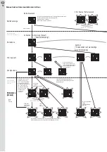
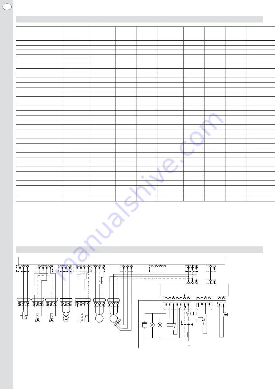
Anschlußplan HLZ 45 mit Elster CM 168
V1
g
e
lb
/g
rü
n
bl
au
br
aun
br
aun
bl
au
bl
au
schw
ar
z
1
2
Elster CM 168
N
FL
N
L1
B1 Ölfeuerungsautomat
EE Externe
Fernentriegelung
F1 Sicherung
max.
10A
GM Gebläsemotor
H1 Signal
Störung
H2 Signal
Betrieb
HS Hauptschalter
LD Flammenfühler
OFV Ölvorwärmer
P1 Betriebsstundenzähler
PM Pumpenmotor
TB
Temperatur- oder Druckbegrenzer
TR Temperatur-
oder
Druckregler
TT Zündtrafo
V1
Magnetventil 1. Stufe
V2
Magnetventil 2. Stufe
Y4A Eurostecker
(4-pol.)
Y5A Eurostecker
(7-pol.)
B1
L1
LD
br
aun
TT
1
2
3
M
bl
au
br
aun
g
e
lb
/g
rü
n
GM
1
2
3
4
5
schw
ar
z
gr
ün
gel
b
B4 S3 T2 T1 N
L1
Y5
N
1/N, PE 230V 50Hz
L1
PE
N
Y5A
HS
F1
TB
L1
N
T1
T2
S3
B4
Anschlüsse
Bauseitig
J
P
TR1
J
P
L1
T8 T7
B5
T6
2
3
T6
T7
T8
J
P
TR2
B5
Y4
Y4A
V2
g
e
lb
/g
rü
n
bl
au
br
aun
1
2
1
2
3
N
bl
au
br
aun
g
e
lb
/g
rü
n
PM
L1
Hall PWM GND
X6
X1
PE
1
4
X4
X9
X7
PE
PE
X8
Bus-
X5
Bus+
N
L1
Y1
PE
Bus-
Bus+
1
2
EE
1
2
H1
H2
h
P1
Y3
Y3A
Kommunikationsinterface (CI)
Y2
g
e
lb
/g
rü
n
4
3
2
1
br
aun
bl
au
schw
ar
z
OFV
N
DI
L1
X2
PE
NV1 NV2
L1
X13
PE
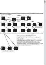
Anschlußplan HLZ 45 mit Elster CM 168
und optischem Flammenwächter
BST-Solutions KLC 2002


