background image

1.

Technical Data

1.1 Range of models

Type

Oil nozzle

Oil throughput 

Fuel power 

(US gal/h 80°H)

m

in kg/h

Q

F

in kW

HLZ 45 AV 17 G1

0,30

0,84 – 1,52

10 – 18

HLZ 45 AV 17 G1

0,35

1,10 – 1,85

13 – 22

HLZ 45 AV 19 G1

0,40

1,18 – 2,02

14 – 24

HLZ 45 AV 19 G1

0,45

1,35 – 2,53

16 – 30

HLZ 45 AV 22 G1

0,55

1,69 – 3,04

20 – 36

HLZ 45 AV 22 G1

0,60

1,94 – 3,37

23 – 40

HLZ 45 AV 24 G1

0,60

2,19 – 3,54

26 – 42

HLZ 45 AV 24 G2

0,65

2,28 – 4,05

27 – 48

HLZ 45 AV 24 G2

0,75

2,45 – 4,38

29 – 52

HLZ 45 AV 24 G2

0,85

2,78 – 4,72

33 – 56

HLZ 45 BV 27 G2

0,85

2,95 – 5,06

35 – 60

HLZ 45 BV 27 G2

1,00

3,29 – 5,56

39 – 66

HLZ 45 BV 31 G2

1,10

4,05 – 6,24

48 – 74

HLZ 45 BV 31 G2

1,25

4,22 – 6,91

50 – 82

Image: Model code  H L Z 45 A V 19 G1

H

R

Herrmann

R

Light oil burner

Z

R

Two-stage

45

R

Series

A

R

Mixing device

V

R

Pre-heater

19

R

Diameter air nozzle (17, 19, 22, 24)

G1

R

Size of blower (G1 HRG 134, G2 RG 148)

1.2 Certification

European Standard (EN) 267:2009, class 3

1.3 Operating range

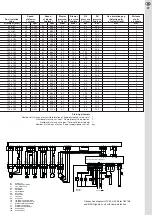
The operating range diagram of an oilburner describes the maximum fur-
nace pressure dependig on the oil mass flow. For a reliable start up the
burner may alternatively be started in the first or second stage. While it is
preferable for the burner to start in the lower power area in the second
stage, a start in the middle or upper power area in the first stage is ad-
vantageous. The diagram below also shows the corresponding starting
points. The range of operation has been determined on a test boiler in ac-
cordance with DIN EN 267:2009 and relates to a height of 100 metres
MSL, as well as to a room temperature of 20ºC. The maximum achievable
firing rate depends on the respective starting resistance of the heating
system. This is influenced by the geometry of the heating system and the
heat exchanger, as well as the flue gas system.

1.4 Serial scope of delivery

1 Oil burner
1 Unit flange
1 Seal for the flange 
2 Odour-proof oil tubes (length 1,500 mm)
4 M8 x 30 fastening screws for unit or shift flange including washers
1 Hexagon key, nominal diameter 4 mm
1 7-pole/4-pole socket – part of Euro female connector in accordance

with DIN 4791:1985-09 (plug connectors for the boiler are not included
in the scope of delivery) 2-pole Rast-5 plug for the remote unlatching

1 Airborne sound absorber
1 Assembly and operating instructions

HLZ 45 AV 19 G1

HLZ 45 AV 17 G1

HLZ 45 AV 22 G1

HLZ 45  BV 27 G2

HLZ 45 AV 24 G2

6,0

6,5

7,0

7,5

HLZ 45  BV 31 G2

HLZ 45 AV 24 G1

Operating range

Fur

nace pr

essur

e in mbar

2. Stufe

(starting point)

1. stage
(starting point)

1. stage

2. stage

Oli mass flow in kg/h

1.5 Fuel

-

Heating oil EL in accordance with DIN 51603-1

-

Heating oil EL, low sulphur, in accordance with DIN 51603-1

-

Heating oil EL, bio 10 (bio heating oil in accordance with 
DIN SPEC 51603-6, heating oil EL, low sulphur, with up to 10% portion
of FAME, corresponding to the quality requirements of DIN 14214)

1.6 Components

Components

Manufacturer

Designation of model

Blower

ebm-papst

HRG 134 / RG 148

Motor

ACC

EB 95 C 35 / 2

Oil pump

Danfoss

BFP 52 E L3

Oil pre-heater

Danfoss

FPHB 5, PTC 50, 
T 60/32, 30-90 W

Ignition

Danfoss/Beru

EBI 4/ZTÜ with flame
monitoring

Flame control

BST-Solutions

Wide Band Flame 
 Detector KLC 2002

Beru

Ignition unit with flame
monitoring, ZTÜ

Firing unit

Elster

CM 168

Communication interface (CI)

Herrmann

CI 1

1.7 Electrical data

Nominal voltage

230 V ~50 Hz

Starting power

approximately 180 W

Operating power 

approximately 130 W–270 W

Contact rating of heat valve and switch 6A~ at minimum

1.8 Acoustic emissions

The HLZ 45 burner is equipped in series with an airborne sound absorber.
By using this sound absorber the sound pressure level can be reduced to a
maximum burner output from 68 dB (A) [without sound absorber] to 60 dB
(A) [with sound absorber]. These values have been detected with a measur -
ing instrument with a degree of accuracy 2 in accordance with IEC 60651
(International Electro-technical Commission) and at a horizontal distance of
2 metres.

1.9 Packing

Individual packaging (carton), base x height: 400 x 400 x 465 mm
Individual weight of the burner without packaging: approximately 12.0 kg
Individual weight of the burner with packaging: approximately 13.0 kg
Collective packaging (18 single cartons on an Euro pallet), base x height:
1,200 x 800 x 1,700 mm
Weight of pallet: approximately 254 kg

2.

Functional description

The HLZ 45 oil burner is designed as two-stage blue flame burner for ope-
ration with EL heating oil. A two-stage gear pump is used for fuel injection.
The injected fuel mass flow depends on the size of the nozzle and the in-
jection pressure adjusted at the respective pressure balance valves of the
respective load stage (6bar<p

E

<25bar). For adjustment of the air volume flow

to the injected fuel mass flow a regulating speed blower is assigned. During
the operation of the burner and before each burner start up the fuel is heated
to a temperature of approximately 70º C in an electric fuel heater. Through
this process, temperature and quality conditioned fluctuations of the fuel
viscosity that have an effect on the spraying process and the fuel flow rate
are decreased. The fuel spray is ignited by an electric spark that is formed
by the application of high voltage between two initiating electrodes. 
Subsequently we will go into the function of the individual sub-systems
in more detail.

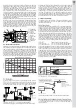
2.1 Mixing device

A blue flame burner mixing device is used to burn the mixture. The fuel
spray that escapes from the nozzle evaporates before the actual reaction
of combustion by a mixture of hot flue gases. The low level of temperature
within the evaporating zone and the water content of the drawn-in flue ga-
ses prevent the formation of soot. The intensity of the backflow is indicated
by the rate of recirculation that measures the proportion of the  recirculated
flow of flue gas of the entire gas mass flow. Low rates of  recirculation fa-
vour the formation of soot. The solid state of soot particles confers a yellow
colour to the flame. An increase in the recirculation of flue gas reduces the
rate of soot formation and ultimately results in a  completely soot-free flame
that emits a hardly visible blue flame to the human eye.

20

EN

Summary of Contents for HLZ 45 AV 17 G1

Page 1: ...ento verticale Leistungsbereich Power range Puissance Campo di potenza 10 82 kW Technische Information Montage und Betriebsanleitung Technical information Assembly and operating instructions Caract ri...

Page 2: ...10 2 Screw plug for the return flow connection of the pump 33 10 3 PC connecting tool 33 10 4 Burner chip card 33 11 Customer service 33 Menustructure of communication interface 34 35 Herrmann blue fl...

Page 3: ...e 52 1 6 Componenti 52 1 7 Dati elettrici 52 1 8 Emissioni sonore 52 1 9 Imballaggio 52 2 Descrizione delle funzioni 52 2 1 Impianto di mescolazione 52 2 2 Ventilatore dell aria per la combustione 53...

Page 4: ...E L3 lvorw rmer Danfoss FPHB 5 PTC 50 T 60 32 30 90 W Z ndeinheit Danfoss Beru EBI 4 Z ndger t mit Flammenerkennung Flammen berwachung BST Solutions Breitbandflammen w chter KLC 2002 Beru Z ndger t m...

Page 5: ...ird zus tz lich das Magnetventil 2 bestromt F r eine korrekte Funktion dieser Schal tung muss der an Druckregler P2 eingestellte Druck stets ber dem an Druckregler P1 eingestellten Druck liegen 2 4 Fl...

Page 6: ...gehen ist nur dann notwendig wenn der Brenner mit dem werkseitig hinterlegten Parametersatz aufgrund extremer rtlicher Gegebenheiten in Bezug auf das Abgassystem die Aussentemperatur oder der H he des...

Page 7: ...rsorgungssystem lleitungsdimensionierung Der Brenner kann wahlweise in einem reinen Einstrangsystem einem Ein strangsystem mit Filter Entl fter Kombination Pumpe wird wie in einem Zweistrangsystem bet...

Page 8: ...ssenstrom starken Tole ranzen unterliegt Daher ist bei einer Inbetriebnahme des Brenners eine Kessel Nennw rmeleistung in kW 16 20 25 35 50 Leitungsinnen in mm 4 4 4 4 4 H in m max zul ssige Leitungsl...

Page 9: ...Rezirkulationsspaltes durch Drehen der Stellschraube entgegen dem Uhrzeigersinn zu einer Intensivierung der Heizgasrezirku lation wodurch der NOx Gehalt der Heizgase abnimmt Mit steigender Rezirkulat...

Page 10: ...Z 45 AV 24 G2 33 54 1 RG 148 0 85 2 78 4 55 24 00 80 HLZ 45 AV 24 G2 33 56 1 RG 148 0 85 2 78 4 72 24 00 80 HLZ 45 BV 27 G2 35 58 1 RG 148 0 85 2 95 4 89 27 00 100 HLZ 45 BV 27 G2 35 60 1 RG 148 0 85...

Page 11: ...120 x 190 47 3 960 78 6 600 6 0 16 3 9 0 23 5 2 0 120 x 190 47 3 960 80 6 780 6 0 17 2 9 0 25 0 2 0 120 x 190 48 4 080 77 6 540 6 0 15 5 9 0 21 0 2 4 120 x 190 48 4 080 80 6 780 6 0 16 6 9 0 22 0 2 4...

Page 12: ...12 DE 7 Explosionszeichnung mit Ersatzteilliste...

Page 13: ...00001 Pos Bezeichnung Art Nr 64 Brennerrohr Unit 125mm lang 10005 00002 Brennerrohr Unit 95mm lang 10005 00007 65 Dichtung f r Flansch AV 10006 00072 66 Rezirkulationsrohr 80x100x150 AV 19 22 und 24 1...

Page 14: ...lercodes zu l schen wiederholten Eingriff von aussen muss der Brenner von der Spannungs 5 x Entst rung innerhalb von 15 min versorgung getrennt werden 11 Flammenbildung w hrend der Vorbel ftung Je nac...

Page 15: ...laseinsatz Lichtrohr verschmutzt reinigen Flammenw chter defekt Flammenw chter tauschen II Z ndeinheit mit Flammenerkennung St rabschaltung ohne Flammenbildung Vorget uschte Flamme durch Fehlerstrom F...

Page 16: ...nnerabmessungen 215 Gebl se HGR 134 233 Gebl se RG 148 132 Gebl se HGR 134 139 Gebl se RG 148 159 Gebl se HGR 134 171 Gebl se RG 148 80 x 80 x 160 80 x 100 x 150 4 3 1 R G H Gebl se 3 3 1 8 4 1 G R Ge...

Page 17: ...ceadapter USB Kabel Bus Kabel Auslesesoftware CD und Bedienungsanleitung unter der Bestell Nr 10042 00013 erh ltlich 10 4 Burner Chip Card Die Burner Chip Card ist ein in den Feuerugsautomaten einsetz...

Page 18: ...ster ohne nderung Liegt kein W rmeanforderungssignal vor werden kurzzeitig Striche angezeigt und dann zur ckgesprungen Bei der Anzeige Betriebszustandes des Feuerungsautomaten wird mit Hilfe der beide...

Page 19: ...n Ausnahme Beim Drehzahleinstellung ist das Turn Around Men deaktiviert Jeweiliger Max Min Wert bleibt auch bei weiterem Drehen erhalten Schwarze durchg ngige Linien zeigen die Bewegungsrichtung zwisc...

Page 20: ...FP 52 E L3 Oil pre heater Danfoss FPHB 5 PTC 50 T 60 32 30 90 W Ignition Danfoss Beru EBI 4 ZT with flame monitoring Flame control BST Solutions Wide Band Flame Detector KLC 2002 Beru Ignition unit wi...

Page 21: ...noid valve V2 is additionally supplied with current to switch into the second stage In order to achieve a correct function of this switching the adjusted pressure at the pressure regulator P2 must alw...

Page 22: ...off cold adjustment However this ac tion only becomes necessary if the burner cannot be put into operation with the factory preset parameters due to extreme local conditions in re lation to the exhaus...

Page 23: ...t is suitable in regard to the exhaust temperatures for the selected exhaust system 3 5 Oil supply system oil pipe dimensions The burner can be selectively operated as a pure one line system a one lin...

Page 24: ...inrichtung Filter Entl fter Kombination 24 EN Boiler s nominal thermal output in kW 16 20 25 35 50 Internal pipe in mm 4 4 4 4 4 H in metres maximum permissible pipe length in metres 0 30 30 30 30 20...

Page 25: ...w counter clockwise would lead to an intensifying of the flue gas recirculation thereby causing a reduction of the NOx content of the flue gas An increasing rate of recirculation would reduce the stab...

Page 26: ...33 54 1 RG 148 0 85 2 78 4 55 24 00 80 HLZ 45 AV 24 G2 33 56 1 RG 148 0 85 2 78 4 72 24 00 80 HLZ 45 BV 27 G2 35 58 1 RG 148 0 85 2 95 4 89 27 00 100 HLZ 45 BV 27 G2 35 60 1 RG 148 0 85 2 95 5 06 27 0...

Page 27: ...3 9 0 23 5 2 0 120 x 190 47 3 960 80 6 780 6 0 17 2 9 0 25 0 2 0 120 x 190 48 4 080 77 6 540 6 0 15 5 9 0 21 0 2 4 120 x 190 48 4 080 80 6 780 6 0 16 6 9 0 22 0 2 4 120 x 190 48 4 080 83 7 020 6 0 17...

Page 28: ...28 EN 7 Expanded view with spare parts list...

Page 29: ...0 10015 00007 Air nozzle MB 824 0 10015 00008 63 Sealing for burner tube 10006 00001 Pos Designation Part Number 64 Burner tube unit 125 mm long 10005 00002 Burner tube unit 95 mm long 10005 00007 65...

Page 30: ...external corrective actions power supply system to delete display 5 x suppressions within 15 minutes of the error code 11 Formation of flame during the pre aeration Depending on start up adjustment an...

Page 31: ...ame detector Exchange the flame detector II Ignition unit with flame monitoring Fault shutdown without the formation Pretend flame created by fault current Remove the moisture in the range of the of a...

Page 32: ...he burner 215 Blower HGR 134 233 Blower RG 148 132 Blower HGR 134 139 Blower RG 148 159 Blower HGR 134 171 Blower RG 148 80 x 80 x 160 80 x 100 x 150 80 x 120 x 190 4 3 1 R G H r e w o l B 3 3 1 8 4 1...

Page 33: ...CD and operating manual is available under the order no 10042 00013 10 4 Burner chip card The burner chip card is a memory element that can be inserted into the firing unit and is used to re paramete...

Page 34: ...ge Button after the change Button without change If no heat request signal exists dashes are displayed for a short period of time and then returned By means of both points the current power stage is s...

Page 35: ...deactivated by adjustment of the blower speed The respective maximum minimum value will also remain with further turning Continous black line shows the direction of movement between the menu levels A...

Page 36: ...RG 148 Moteur ACC EB 95 C 35 2 Pompe fioul Danfoss BFP 52 E L3 R chauffeur fioul Danfoss FPHB 5 PTC 50 T 60 32 30 90 W Unit d allumage Danfoss Beru EBI 4 MKZ avec d tection de flamme D tecteur de fla...

Page 37: ...me met en plus l lectrovanne 2 sous tension Pour que ce circuit fonctionne correctement il faut toujours que la pression r gl e sur le r gulateur de pression P2 soit toujours sup rieure celle r gl e...

Page 38: ...n est n cessaire que lorsqu il n est pas possible de mettre le br leur en service tel que param tr en usine en raison d imp ratifs locaux extr mes visant le circuit des gaz d chappe ment la temp ratu...

Page 39: ...fioul dimensionnement de la conduite de fioul Le br leur peut tre exploit au choix avec un syst me strictement mono tube un syst me monotube avec tandem filtre dispositif de d gazage la pompe est expl...

Page 40: ...ner l indice de 40 FR Puissance calorifique nominale de la chaudi re en kW 16 20 25 35 50 int rieur de conduite en mm 4 4 4 4 4 H en m Longueur max admissible de conduite en m 0 30 30 30 30 20 1 30 30...

Page 41: ...donc le flux de gaz br l s recircul s En cons quence la te neur en NOx des gaz br l s augmente un peu Inversement un agran dissement de la fente de recirculation en tournant la vis dans le sens an ti...

Page 42: ...l du fioul Gicleur Tube Mod le de br leur 1er niveau 2e niveau niveau Soufflerie fioul 1er niveau 2e niveau d air foyer kW kW USgal h 80 H kg h kg h mm mm HLZ 45 AV 17 G1 10 18 2 HRG 134 0 30 0 84 1 5...

Page 43: ...fiou chelle de r glage gicleur air recirculation 1er niveau 2e niveau 1er niveau 2e niveau 1er niveau 2e niveau de l ouverture r elle gicleur de fioul mm x l mm tr mn tr mn mbar mbar bar bar mm mm 80...

Page 44: ...44 FR 7 Vue clat e avec liste des pi ces de rechange...

Page 45: ...d air MB 824 0 10015 00008 63 Joint pour tube foyer 10006 00001 Pos D signation N de r f 64 Tube foyer Unit longueur 125 mm 10005 00002 Tube foyer Unit longueur 95 mm 10005 00007 65 Joint pour bride A...

Page 46: ...fa on instable et Pour effacer l affichage des codes de d faut requiert une intervention r p titive de il faut d brancher le br leur du secteur l ext rieur 5 d parasitages en l espace de 15 min 11 Fo...

Page 47: ...de flamme d fectueux Remplacer le detecteur de flammes II Unit d allumage avec d tection de flamme Coupure sur d rangement sans formation Un courant perturbateur d l humidit Supprimer l humidit dans...

Page 48: ...ntilateur HGR 134 233 Ventilateur RG 148 132 Ventilateur HGR 134 139 Ventilateur RG 148 159 Ventilateur HGR 134 171 Ventilateur RG 148 80 x 80 x 160 80 x 100 x 150 80 x 120 x 190 4 3 1 R G H Ventilate...

Page 49: ...mprenant l adaptateur d interface le c ble USB le c ble bus le logiciel de lecture CD et la notice d utilisation 10 4 Carte puce du br leur La carte puce du br leur est un l ment m moire introductible...

Page 50: ...s modification Touche sans modification En l absence d un signal de demande de chaleur tous les traits s affichent bri vement puis s teignent successivement Concernant l affichage de l tat de service...

Page 51: ...e Exception Lors du r glage de la vitesse le menu giratoire est d sactiv La valeur max min respective demeure m me pendant la poursuite de la rotation Des lignes noires continues indiquent le sens de...

Page 52: ...14214 1 6 Componenti Componente Produttore Modello Ventilatore ebm papst HRG 134 RG 148 Motore ACC EB 95 C 35 2 Pompa del combustibile Danfoss BFP 52 E L3 Preriscaldore del combustibile Danfoss FPHB...

Page 53: ...el bruciatore al primo stadio di pressione si provvede la valvola magnetica 1 con corrente Attivando in pi la valvola magnetica 2 si arriva al secondo stadio di pres sione Per poter garantire un funzi...

Page 54: ...che il bru ciatore non pu essere messo in funzione con i parametri prestabiliti in fabbrica a cause delle condizioni estremamente severi rispetto al sistema di scarico la temperatura esterna o l alte...

Page 55: ...essario chiudere il ma nicotto di recupero usando il tappo di chiusura e rimuovere la vite di cam bio nel condotto di collegamento tra lato pressione e lato aspirazione Per evitare anomalie del brucia...

Page 56: ...i tolleranze Per questo necessario eseguire IT Potenza calorifica nominale della caldaia in kW 16 20 25 35 50 interno del condotto in mm 4 4 4 4 4 H in m Max lunghezza del condotto permessa in m 0 30...

Page 57: ...colo In questo modo si pu regolare la portata di gas combusti In se guito il contenuto di NOx nei gas combusti aumenta leggermente E vice versa girando la vite di regolazione in senso antiorario si in...

Page 58: ...2002 Potenza di Potenza di Portata del Portata del Tipo del accensione accensione Avvio Ugello del combustibile combustibile Ugello Tubo del bruciatore 1 stadio 2 stadio 1 2 stadio Ventilatore combust...

Page 59: ...ilatore ventilatore ventilatore combustibile combustibile scala di regolazione dell aria ugello ricircolo 1 stadio 2 stadio 1 stadio 2 stadio 1 stadio 2 stadio larghezza reale del combustibile mm x l...

Page 60: ...60 IT 7 Disegno esploso con lista parti di ricambio...

Page 61: ...icolo 64 Tubo del bruciatore Unit lunghezza 125 mm 10005 00002 Tubo del bruciatore Unit lunghezza 95 mm 10005 00007 65 Guarnizione per flangia AV 10006 00072 66 Tubo di ricircolo 80x100x150 AV 19 22 e...

Page 62: ...arico d aria 10 Errore blocco a distanza Il bruciatore funziona in modo instabile Per eliminare la indicazione degli errori bisogna intervenire spesso al di fuori si deve staccare il bruciatore da ret...

Page 63: ...to pezzo di vetro della luce della fiamma del tubo sporco del tubo Il pirostato difettoso Cambiare il pirostato II Unit d accensione con riconoscimento della fiamma Interruzione errore senza accension...

Page 64: ...Ventilatore HGR 134 233 Ventilatore RG 148 132 Ventilatore HGR 134 139 Ventilatore RG 148 159 Ventilatore HGR 134 171 Ventilatore RG 148 80 x 80 x 160 80 x 100 x 150 80 x 120 x 190 4 3 1 R G H Ventila...

Page 65: ...adattatore d interfaccia all interfaccia USB del PC L attrezzo di collegamento consiste dall adattatore d interfaccia cavo USB cavo di bus software di selezione CD delle istruzioni d uso e pu essere o...

Page 66: ...enza cambiamento Se il segnale di richiesta del calore assente sar visualizzata brevemente una barra dopo di che si salter all indietro Il display dello stato d esercizio dell impianto di combustione...

Page 67: ...ione del numero di giri il turn around menu deattivato L attuale max min rimane anche durante la rotazione sucessiva Linee nere continue indicano la direzione di movimento tra i livelli di menu Un sal...

Page 68: ...Herrmann GmbH u Co KG M Liststra e 8 M D 71336 Waiblingen Tel 49 0 7151 98928 0 M Fax 49 0 7151 98928 49 E Mail info herrmann burners de M Internet www herrmann burners de...

Reviews: