23
EN
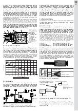
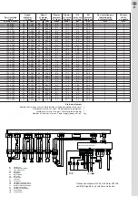
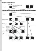
Program flow of Elster CM 168 control box;
3.
Initial operation
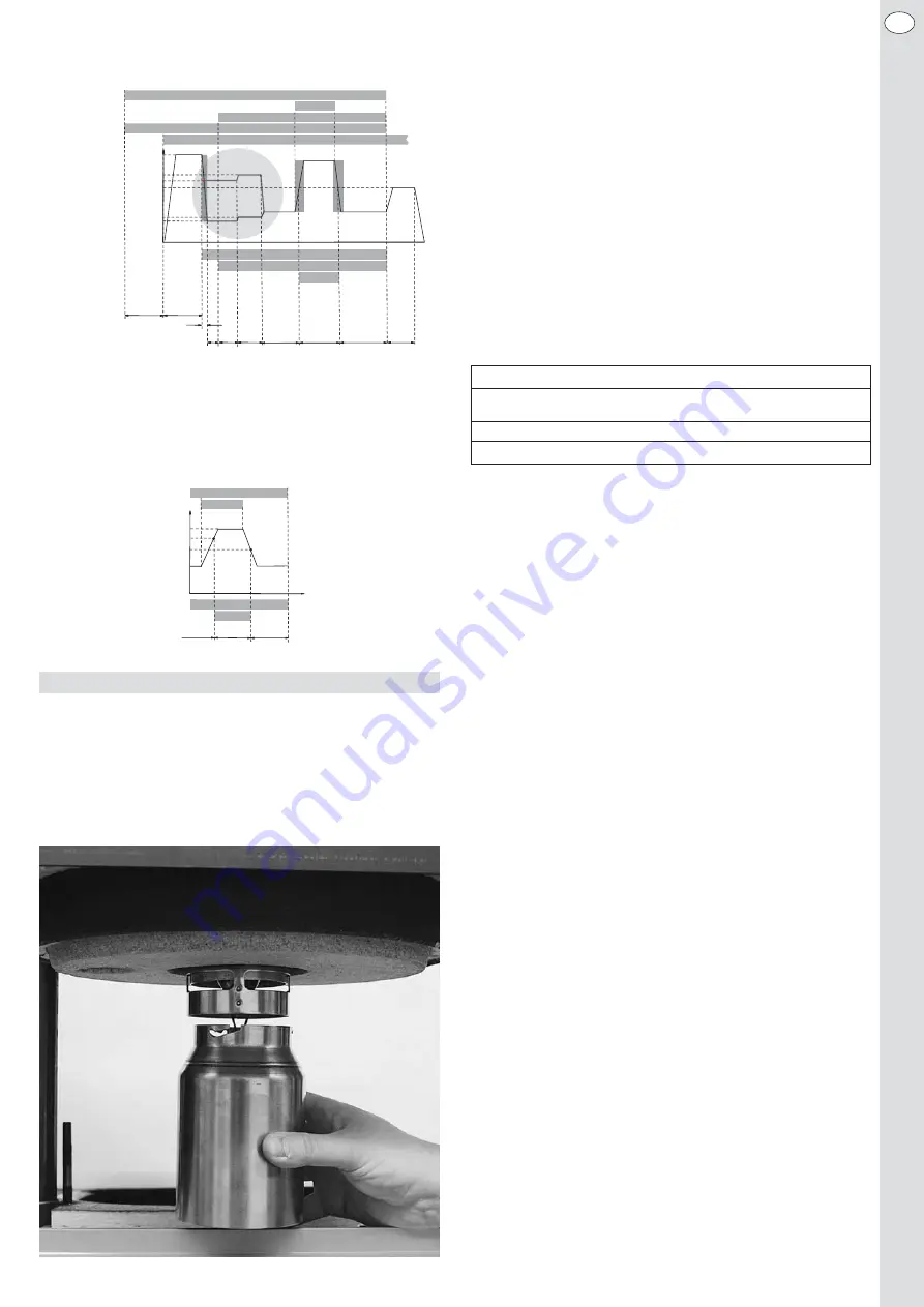
3.1 Assembly of the burner
-
Assemble the flange, including the burner tube, by means of the
attached M8 screws, onto the heat generator.
-
Insert the burner into the flange and fasten it by means of the service
screw. The opening of the recirculation should not be covered by the
insulation of the combustion chamber.
-
Put on the recirculation tube and twist it into the bayonet socket until
it locks.
3.2 Electricity supply
While carrying out electrical installations you must observe the relevant
provisions of VDE (Association of German Electro-technical Engineers),
SEV (Swiss Association of Electro-technical Engineers) or ÖVE (Austrian
Association of Electro-technical Engineers). Power supply: 230 V~ 50 Hz
10 A. The burner must be connected to the standard connectors of the
boiler, i.e. in accordance with DIN 4791:1985-09 through a 7-pole and 4-
pole Euro plug, and for the remote unlatching through a 2-pole Rast-5
plug. The burner’s cable must be shortened to such an extent that the
connector must be loosened to swing out the burner.
Details of wiring may be taken from the wiring diagram in chapter 6. The
factory will deliver the burner together with the Euro-connector (female
plug).
3.3 Combustion chamber – minimum dimensions
In order to ensure reliable operation and low pollutant emissions the geo-
metry of the combustion chamber must meet the test flame tube stan-
dards in accordance with DIN EN 267:2009.
3.4 Exhaust gas system
The burner is designed to operate in a dependent room air mode, as well
as in an independent room air mode. To operate the burner in dependent
room air mode we would recommend the installation of a draft limiter into
the flue gas system in order to ensure a constant pressure in the com-
bustion chamber. The adjustable low pressure in the combustion cham-
ber, which may be set on the draft limiter in comparison with the ambient
pressure, should be –0.1 mbar.
To operate the burner in independent room air mode, it may be connected
to the air exhaust turnout of an air exhaust system by using an air intake-
connecting piece (Ø 50 mm). We recommend an air exhaust system with
a maximum length of 14 metres and 3 (maximum) installed sharp bends.
It is allowed to use a coaxial tube with a diametric pairing of Ø 80/125
mm up to a firing performance of 30 kW. A coaxial tube with a diametric
pairing of Ø 100/150 mm is recommended for the performance range
above 30 kW. The exhaust pipe must be gas-proof, insensitive to mois-
ture, resistant to corrosion and acids, and permitted for exhaust tempe-
ratures up to 120° Celsius. If you operate the burner in independent room
air no draft limiter should be installed into the exhaust pipe. In addition,
you must ensure that the heating boiler used is a boiler that is suitable in
regard to the exhaust temperatures for the selected exhaust system.
3.5 Oil supply system, oil pipe dimensions
The burner can be selectively operated as a pure one-line system, a one-
line system with filter-aspirator combination (the pump is operated similar
to a two-line system), or a two-line system.
The burner has been pre-set in series for a two-line system. When con-
verting the pump to a one-line operation make sure to seal the return
piece with a drain plug and remove the shift screw in the junction canal
between the pressure and the suction side.
In order to avoid any malfunction of the burner caused by the oil supply
system we would recommend operating the burner in a pure one-line
system with filter-aspirator combination. In this case you should consider
the following points:
• The maximum suction height without a booster pump should not ex-
ceed 3.5 metres.
• Up to a nominal thermal output of the boiler of 50 kW we would recom-
mend an oil pipe with an internal diameter of 4 mm for the one-line sys-
tem with filter-aspirator combination.
• The pipes should be arranged in such a manner that the boiler door, to-
gether with the burner, can be traversed by 90°.
• In front of the flexible oil pipes you must install a valve at the end of the
rigid oil pipes (already integrated in commercial filter-aspirator combi-
nations).
• A filter-aspirator combination must be installed before the burner. An
insert of 20-75 μm sintered plastic should be used for boiler capacities
of up to 40 kW, while for boiler capacities of more than 40 kW it should
be a sieve with a fineness of 100-150 μm.
• The highest point of the oil pipe should not exceed 3.5 metres above
the suction pipe of the oil tank.
• The pipes must be installed in such a manner that no liquid may be al-
lowed to escape from the container.
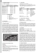
Furnace - minimum dimensions according to DIN EN 267:2009
Oil flow
Diameter respectively
Depth from the baffle
height and width
plate
1,0 - 2,0 kg/h
Ø 225 mm
250 - 350 mm
2,0 - 6,0 kg/h
Ø 300 mm
350 - 612 mm
time t
t
wpri
t
pop
t
fs
t
s
t
pri
t
prp
t
h
Start
e
n
prp
n
fs,2
n
i,2
n
pop
n
fs,1
n
i,1
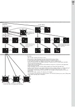
PROGRAMME SEQUENCE
t
h
Heating up time, oil pre-heater
t
prp
/ n
prp
Prepurge time/blower speed
t
wpri
/ n
i
Waiting time pre-ignition/blower speed pre-ignition and safety time
t
pri
/ n
i
Pre-ignition time/blower speed pre-ignition and safety time
t
S
/ n
i
Safety time/blower speed pre-ignition and safety time
t
fs
/ n
fs
Stabilization time/blower speed
n
1
/ n
2
Blower speed at stage 1 and 2
t
pop
/ n
pop
Postpurge time/blower speed
Stage 2
Stage 1
Stage 1
Start stage 1
stage 2
Parameteri-
zable
actuating
ramp V2
Flame signal
Oil pre-heater
Heat demand stage 1
Heat demand stage 2
Thermostat oil pre-heater
Blower speed n
Oil pump motor
Solenoid valve V1
Solenoid valve V2
Heat demand stage 1
Heat demand stage 2
Blower speed n
Blower speed stage 2, n
2
Blower speed at start-up
V2, n
Blower speed at shutdown V2, n
Blower speed stage 1, n
1
Solenoid valve V1
Solenoid valve V2
on,V2
off,V2
Stage 1
Stage 1
Stage 2
time t


