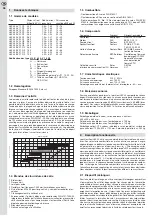
3.6 Burner adjustment
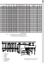
Each burner has been pre-adjusted by the factory in accordance with ba-
sic adjustment table on page 26, 27. When carrying out initial operation
this basic setting to local conditions should be adopted. It should be also
taken into account that the injected oil mass flow is subject to heavy
tolerances at a pre-determined pressure. It is therefore absolutely
• If the highest level of the oil in the tank is above the oil pump of the bur-
ner you must install a solenoid valve at the highest point of the oil pipe,
and as close as possible to the oil tank.
• The oil pipe and the connection to the burner must meet the current
provisions. It is absolutely imperative that you check the existing oil
supply, as from the time of oil tapping from the oil tank.
* H = Maximum suction height in metres (low sulphur heating oil EL, oil
temperature >10 C, up to 700 metres MSL, 1 filter, 1 check valve,
6 bends 90°).
For other plant requirements (such as suction height, pipe lengths and
boiler nominal thermal outputs) you should consider the planning instruc-
tions in the sales catalogue (assembly of oil pipes) and in the attached
diagrams of conduit dimensioning.
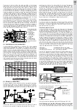
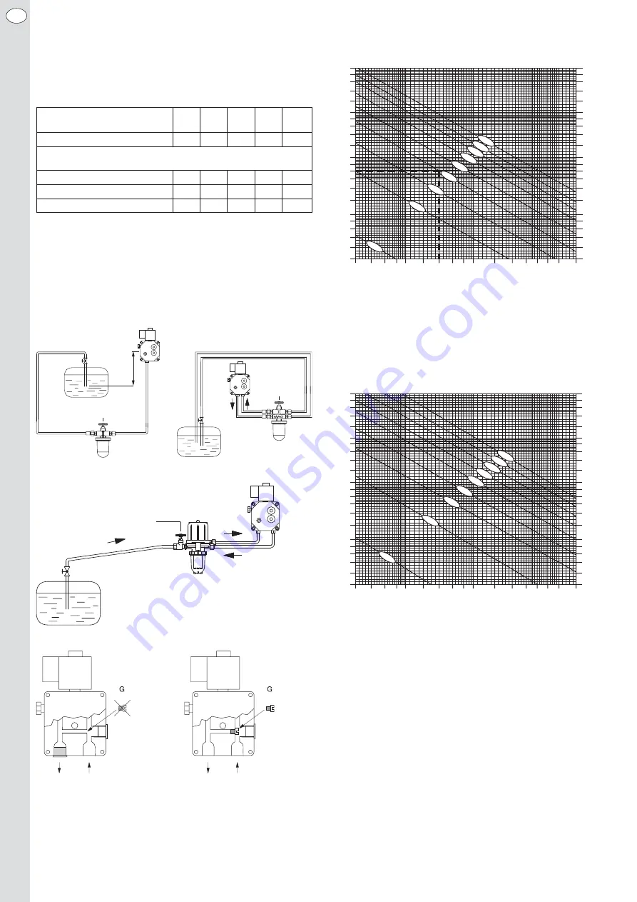
Oil supply system
Pure one-line system. Two-line system.
Adjustment at the oil pump for a one- and two-line system.
De-aeration of the oil supply system
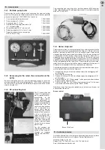
For de-aeration of the oil supply system we would recommend the con-
nection of a suction pump at the low pressure measuring connecting
piece. If no flame is formed after the course of the starting sequence you
should repeat this process by eliminating the lockout of the firing unit. In
order to avoid an overloading of the ignition unit, as well as damage to
the pump by air locks, you should eliminate the lockout of the burner a
maximum of only 3 times. If a complete de-aeration of the oil supply has
not been occurred until then we would recommend once more deploying
an external suction pump for the de-aeration.
Absperreinrichtung
Filter
Absperr-
einrichtung
Filter
H
max
=
3,5 m
Absperreinrichtung
Filter-Entl
ü
fter -
Kombination
24
EN
Boiler’s nominal thermal output
in kW
16
20
25
35
50
Internal pipe Ø in mm
4
4
4
4
4
H* in metres
maximum permissible pipe
length in metres:
0
30
30
30
30
20
1
30
30
30
23
15
2
30
28
23
16
10
[l/h]
20
18
16
14
12
10
9
8
7
6
5
4,5
4
3,5
3
2,5
2
1,8
1,6
1,4
1,2
1
6 7 8 9 10
12
14
16 18 20
25 30 40
50 60 [m]
[m/s]
0,442
0,398
0,354
0,310
0,243
0,221
0,199
0,177
0,155
0,133
0,111
0,100
0,088
0,077
0,066
0,055
0,044
0,039
0,035
0,030
0,026
0,022
+4
m
+3
m
+2
m
+1
m
+/-0
m
–1 m
–3 m
–4 m
Unrolled length of suction pipe
Diagram of dimensions for suction pipes, dimension Ø 4/6 mm
Range of application: 1-10 liters/h, oil temperature: 0-10 °C (outdoor tank)
–2 m
[l/h]
20
18
16
14
12
10
9
8
7
6
5
4,5
4
3,5
3
2,5
2
1,8
1,6
1,4
1,2
1
6 7 8 9 10
12
14
16 18 20
25 30 40
50 60 [m]
[m/s]
0,442
0,398
0,354
0,310
0,243
0,221
0,199
0,177
0,155
0,133
0,111
0,100
0,088
0,077
0,066
0,055
0,044
0,039
0,035
0,030
0,026
0,022
+4
m
+3
m
+2
m
+1
m
+/-0
m
–1 m
–2
m
–3 m
–4 m
Unrolled length of suction pipe
Diagram of dimensions for suction pipes, dimension Ø 4/6 mm
Range of application: 1-10 liters/h, oil temperature: > 0-10 °C (indoor tank)
+ = Height of admission; − = Height of suction
Reading sample:
Given:
Flow rate 4 litres/hour, suction height 1 metre
Searched: Most possible unrolled length of suction pipe
Solution:
From diagram
14 metres
Notice:
The first stage is decisive in determining the pipe diameter.
However, you must reckon with the full load (second stage) quantity for
control of the maximum length of pipe in accordance with the suction
height.
If the dimensions of the pipe are not sufficient for a suction operation (i.e.
the suction pipe is longer than indicated in the pipe dimensions diagram),
you should use a booster pump. Make sure that the oil pipe will not be in-
creased.
Applicable for:
Extra Light heating oil, up to 700 metres MSL; maximum
length of pipe: 30 metres
The diagram includes:
1 filter, 1 check valve, 6 bends at 90°, 40 mbar
Notice: The correcting diagram for suction heights should be considered
at sea levels above 700 metres.
One-line system with a
filter de-aerator combination.
One line
installation
Two line
installation
Valve system
Valve system
Valve system
Combination of
filter/exhauster


