background image

I n s t a l l a t i o n ,   O p e r a t i o n ,   &   M a i n t e n a n c e   M a n u a l

4

www.herrmidifier-hvac.com

Herrtronic

®

 Model 6500

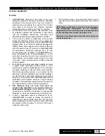
SECTION II UNIT OPERATION

Basic Operation Overview

Controlled  humidification  requires  a  very  precise  control 

system. The Herrtronic 6500 utilizes a microprocessor 

based control system to monitor performance and maintain 

capacity. The humidifier evaluates the operation and alerts 

the operator to problem conditions and prevents undesirable 

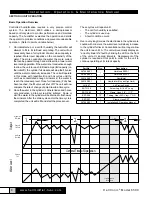
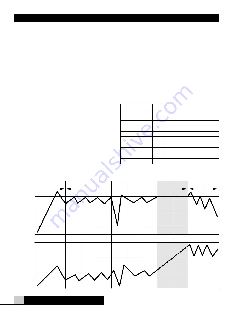
operation.  (Refer to points on table below.)

1. 

On initial start-up or a call for humidity, the humidifier will 

attempt to fill to its full load amp rating. The unit will not 

necessarily have a full cylinder of water when capacity is 

reached. Water level depends on the conductivity of the 

water. The more conductive the water, the more current 

that can be passed through and will result in a lower water 

level during operation. If the water is not conductive enough 

to allow the unit to reach full load amps (full capacity) on 

the initial fill, the cylinder full module will stop the fill valve 

until the water conductivity increases. The unit will operate 

in  this  mode  with  repetitive  fill  and  boil  cycles  until  the 

unit has concentrated enough minerals in the water to 

reach the rated amp level. Once full load amp (FLA) has 

been reached, the fill valve will shut off. The unit will now 

compare the rate of change of amp draw to a time cycle. 

2.  Once the water in the cylinder is mineral laden and hence 

very conductive, a drain cycle will be initiated.  Some or 

all of the water in the cylinder will be drained to flush away 

the minerals. After the drain cycle and/or the time cycle is 

completed, the unit will refill and start the process over.

These cycles will repeat until: 

• 

The call for humidity is satisfied. 

•  The cylinder is used up. 

•  A fault condition occurs. 

3. 

Over a very long time, as the electrodes in the cylinder are 

coated with minerals, the water level will slowly increase 

to the cylinder full level. Concentration will no longer allow 

the unit to reach FLA.  The unit will eventually display an 

“end of cylinder life” fault by blinking the LED on the front 

of the unit at ½ second intervals.  Replacement of the 

cylinder is required at this point in order for the unit to 

continue operating at its rated capacity.

Part No.

Qty.

Description

267460-001

1

Herrtronic 6500-1

267460-002

Herrtronic 6500-2

265160-001

1

Humidistat

265160-001

1

Humidistat (Use as High Limit)

AH-297

1

Air Proving Switch

EST-1138

2

Screw, Lag 5/16 x 2” Long

EST-1563

2

Clamp, Hose, 3/4” - 1 1/2”

EST-206

12”

Tubing, Clear PVC Vinyl, 1” OD

EST-207

1

Clamp, Hose SST

267949-001

1

Installation & Operation Manual

General Time of Operation

1.

2.

3.

High Drain

Threshold

Capacity

Set Point

Low Drain

Threshold

Cylinder

Full

Steadily Increase

Water Level

W

at

er L

ev

el

Output

Summary of Contents for Herrtronic 6500 Series

Page 1: ...H E R R M I D I F I E R w w w h e r r m i d i f i e r h v a c c o m Herrtronic 6500 Series Electrode Steam Humidifiers READ AND SAVE THESE INSTRUCTIONS...

Page 2: ...res 5 Engineering Application 6 SECTION III INSTALLATION INSTRUCTIONS Mounting 7 Plumbing 7 Steam Distribution 8 Wiring 9 Supply Power 9 Control Circuit Connections 9 SECTION IV OPERATING INSTRUCTIONS...

Page 3: ...th this number may be returned to HERRMIDIFIER for replacement Incidental expenses such as cost of transporting the humidifier to HERRMIDIFIER or labor associated with removal replacement of the parts...

Page 4: ...reached the fill valve will shut off The unit will now compare the rate of change of amp draw to a time cycle 2 Once the water in the cylinder is mineral laden and hence very conductive a drain cycle...

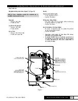
Page 5: ...nder life may be higher or lower depending on the exact composition of your water supply Key Features Adjustable Setpoints See Figure 13 Page 13 Capacity Range 50 100 Preset at 100 Low Drain Threshold...

Page 6: ...plest application is to utilize the steam generated by the 6500 unit to discharge it directly into the HVAC system ductwork In this application a steam pipe is preferably installed in the system ductw...

Page 7: ...lts according to the dimensions in Figure 3 4 Hang the unit on the wall and secure the bolts Be sure the unit is level and mounted directly to the wall into wood studs at least 2 thick or equivalent O...

Page 8: ...talling in the side of the ductwork make sure the unit is positioned to allow condensate to drain back down the steam hose to the steam generator The duct distributor pipe has a built in pitch to allo...

Page 9: ...rtronic Model 6500 Control Circuit Connections WARNING Do NOT install any controls inside the HERRMIDIFIER 6500 cabinet Installations of any extraneous devices inside the electrical compartment may ca...

Page 10: ...___________ ____________________________________________ Humidifier Installer Company Checklist completion date DRAIN RESERVOIR BALANCE OF DRAIN LINE TO BE 1 MIN I D DRAIN WATER TEMPERATURE IS SUITABL...

Page 11: ...l 6500 CYLINDER FULL INTERFACE ELECTRODE RELAY FILL VALVE ADJUSTING SCREW POWER TERMINAL BLOCK TRANSFORMER 24VAC COM TERMINAL BLOCK TERMINAL STRIP MAIN CIRCUIT BOARD AUXILIARY RELAY DRAIN SWITCH COVER...

Page 12: ...Figure 12D Herrtronic Model 6500 CYLINDER FULL ELECTRODE WIRE 26 POWER WIRE 33 POWER WIRE 32 115V UNIT CYLINDER FULL ELECTRODE WIRE 26 POWER WIRE 33 POWER WIRE 32 230V UNIT A C E D E C Maintenance To...

Page 13: ...cted to a complete operational test prior to shipment All circuit board adjustments are made at the factory and should not be adjusted beyond the guidelines set in this troubleshooting guide without f...

Page 14: ...utput over a 24 hour timeframe This alarm indicates a need to change the cylinder that the water supply is low in conductivity or that a foaming condition exists End of cylinder life Cylinder life is...

Page 15: ...over concentration and foaming Check restriction in fill line Adjust the metering fill valve to allow greater flow of water See Figure 11 Have water analyzed If iron content is greater than 1 mg lite...

Page 16: ...If water is going down the overflow and the water level is low Check to ensure that static pressure in the duct is not forcing water down the overflow instead of allowing water to enter the cylinder...

Page 17: ...ASSIS CYLINDER FULL INTERFACE TRANSFORMER AUX AIR PROVING SWITCH 6 8 10 5 4 2 1 1 2 3 4 5 6 7 8 9 10 TOROID 11 R1 RELAY R2 ELECTRODE RELAY FILLVALVE DRAINVALVE J1 CF ELECTRODE HUMIDISTAT 24VAC ELECTRO...

Page 18: ...530 1845 GT 118 GT 116 FILL SUB ASSEMBLY 138586 001 GT 120 EST 207 EST 1533 3 DRAIN SUB ASSEMBLY 1095 EST 1012 GT 262 EST 596 EST 207 EST 003A GT 335 EST 1512 GT 322 EST 1225 KIT EST 353 EST 105A 2675...

Page 19: ...Drain reservoir kit EST 1512 Transformer 115 230V to 24VAC EST 1530 Terminal block EST 1533 3 Drain valve kit EST 1618 Tubing 1 O D silicone EST 207 Clamp EST 207 Hose clamp SS EST 353 Bushing short 3...

Page 20: ...Form No 267949 001 Rev 11 16 HERRMIDIFIER 101 McNeill Rd Sanford NC 27330 P 800 884 0002 F 800 458 2379 www herrmidifier hvac com cs herrmidifier hvac com HERRMIDIFIER 2016 All Rights Reserved...

Reviews: